 November 14, 2022 -- Evolution or Devolution? You Decide
I've been trying to optimize the rig I play out with, hoping to maximize the different options for making noises while still making it portable, and most of all, reliable. The Rackette worked pretty well, but its weakest link was the Boss GP-10, because its guitar models were a little dated, and since I got an SY-1000, it's hard to go back. And my first go at using the SY-1000 and controlling it with a secondary pedalboard worked, but was less than fun to fit onto a stage. And I also wanted to still use my synth, because I've made some usable patches, for fiddle sounds, accordion, saxophone, etc. For some reason, it didn't dawn on me until recently that with the Morningstar, I can do everything that all those FS-7 footswitch pedals were doing, just by switching to a new bank of presets, and if I got a couple of heavy-duty Boss expression pedals (I already had one I wasn't using, and found another pristine one on ebay for a decent price), I could have what I needed, and it would all fit into that Pedaltrain flight case.
To use the GR-55 synth without the GP-10, I didn't need a case as big as the Rackette's, and, being without a day job, I had no budget for new stuff, which compelled me to work with what I had. Luckily, I had a smaller 4U rack case, and with a little shoehorning, I managed to make something workable, fairly lightweight, and something my amp can sit on, to reduce its stage footprint.
So here's what we're looking at now:
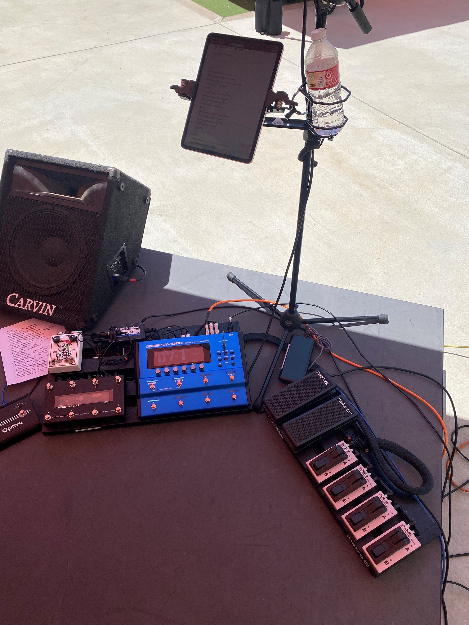
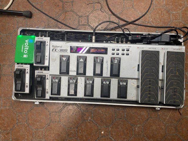
 The view from the stage
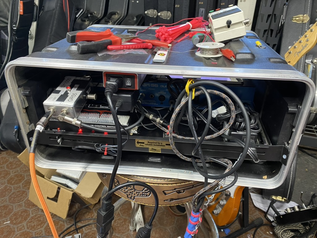
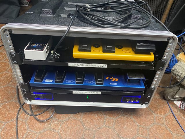
and the view of the little rack:
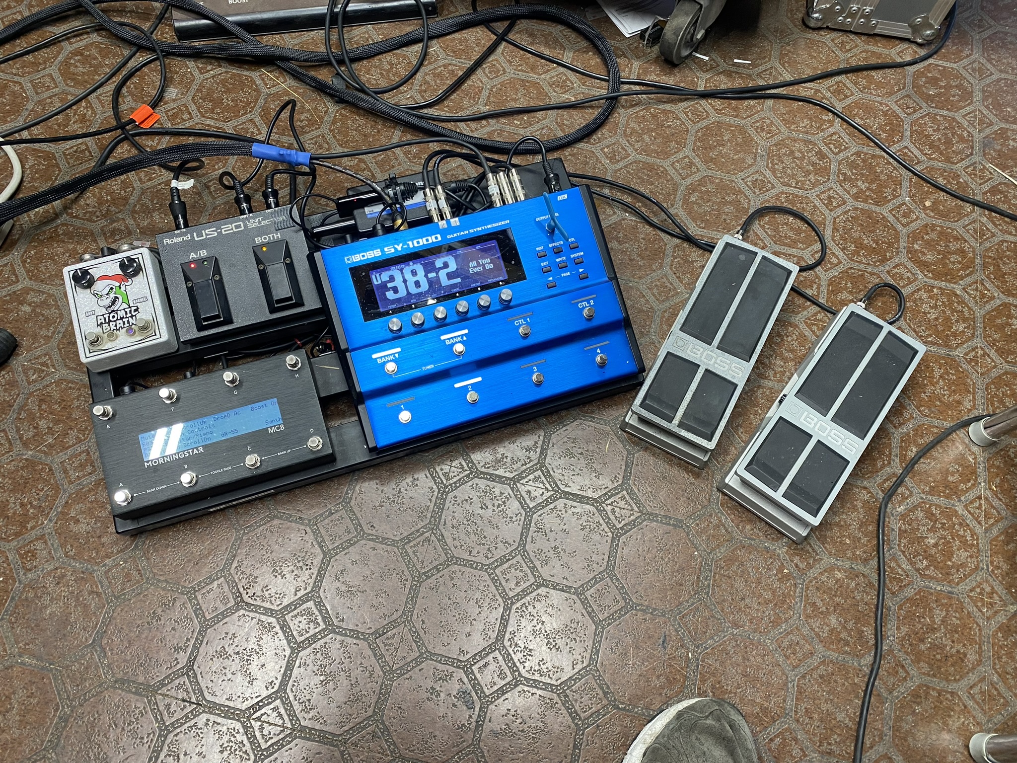
- A Pedaltrain 2 (they now call it the Novo 24) pedalboard with only a few things on it:
- Boss SY-1000
- Nocturne Atomic Brain (in the SY-1000's effects loop)
- Morningstar MC8 MIDI foot controller (to control everything via MIDI)
- Roland US-20 GK ABY switch for sending synth/processor data to both the SY-1000 and the GR-55
- Yamaha BT-01 Bluetooth MIDI adapter to communicate with the iPad that also controls everything
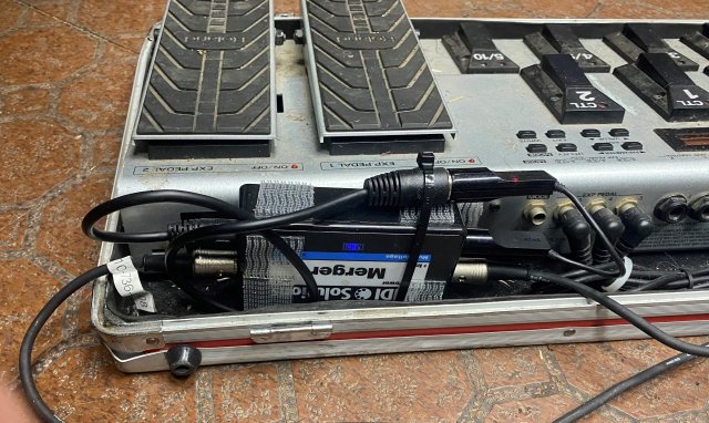
- MIDI Solutions MIDI Merger (2 MIDI Ins, 2 MIDI Outs) so the Yamaha and the Morningstar can peacefully coexist
- Voodoo Labs Pedal Power Plus (hidden under the board) to power the Atomic Brain and the MC8 (kind of overkill, but I had it on hand and it certainly does the job well)
- Boss PS-120 to power the SY-1000
- 2 Boss FS-30 Expression pedals, plugged into the SY-1000, one for volume, one for string-bending, pitch changes, and cross-fades on the synth.
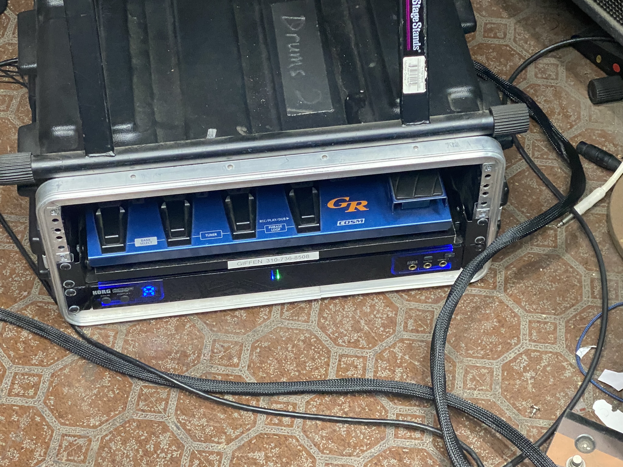
- SKB 4U portable rack that contains:
- Slideout shelf with the GR-55 mounted on it
- Korg Pitchblack PB05 rackmount tuner (plugged into Guitar Out jack on GR-55)
- Voodoo Labs Control Switcher MIDI-controlled switch
- Repurposed loop switcher to select the audio source that gets fed to the amp
- JouleBar (red) power strip/surge protector (an impulse purpose at a NAMM Show that's finally found a use) Dual-Locked to the roof inside the rack; the tuner and the GR-55 power supply are plugged into it
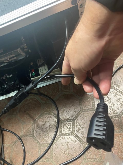
- IEC Y-cable that provides power to the JouleBar and an outlet for the amp (the amp sits on top of the rack on stage)
- A 25ish-foot snake that contains 3 cables:
- MIDI cable (from SY-1000 MIDI Out to Control Switcher MIDI In; the GR-55 can't act as a MIDI Thru, but the Control Switcher can, so there's another MIDI cable from the Control Switcher to the GR-55's MIDI In)
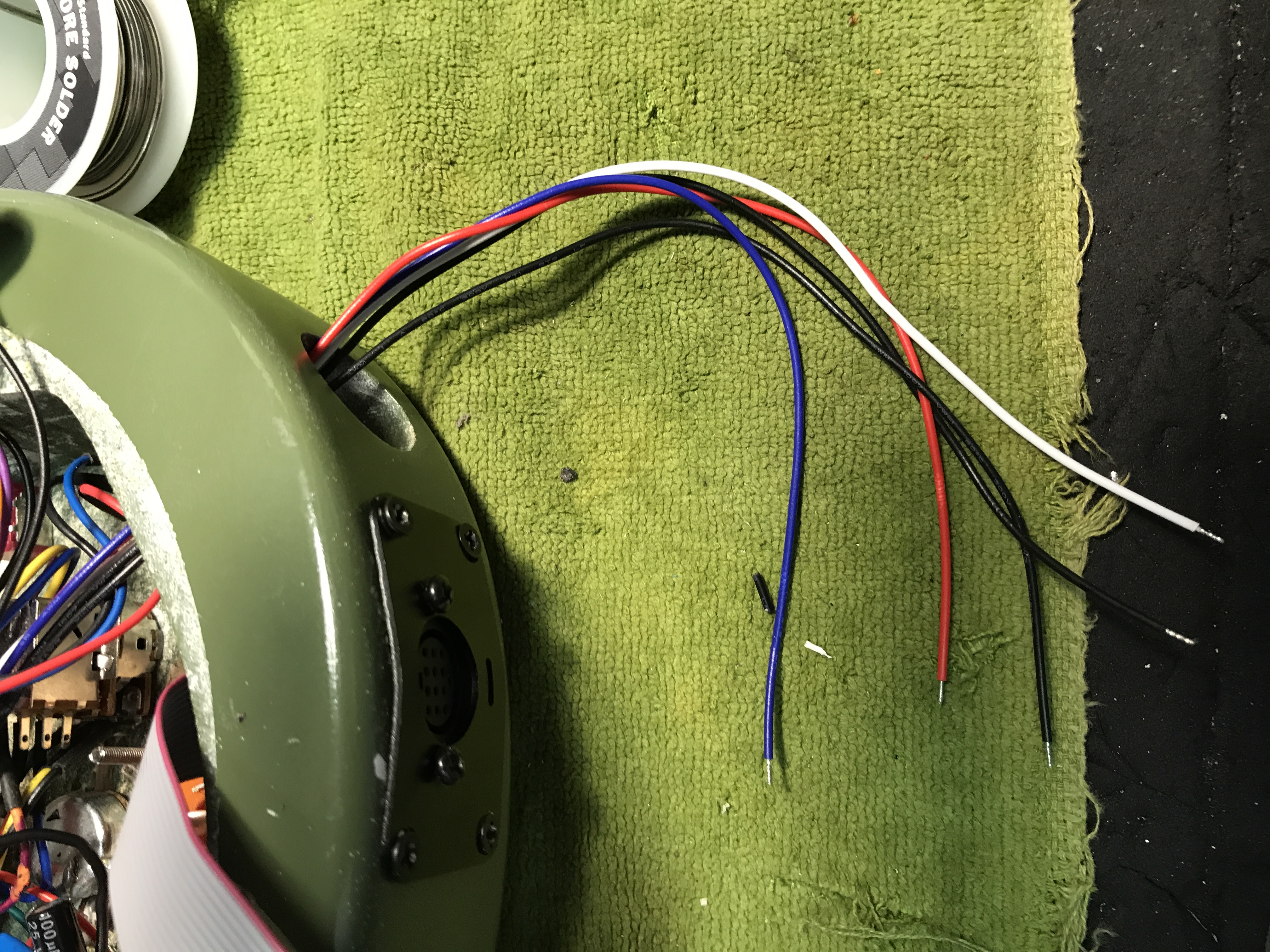
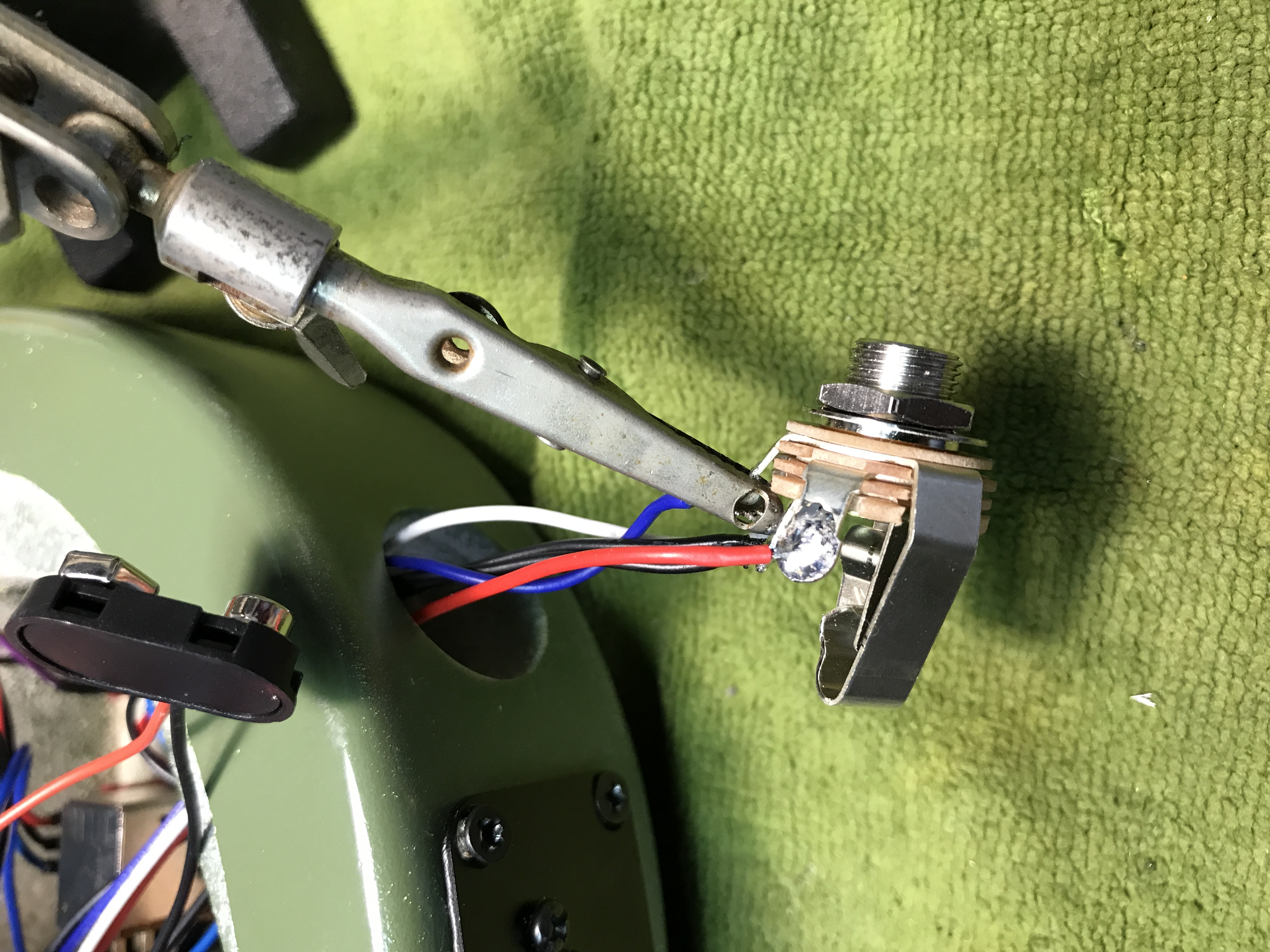
- Audio cable that runs from the SY-1000's Mono Out (yes, I could do stereo, but no one really cares if it's mono or stereo, and it's just more stuff to bring to a gig, so forget that) that goes to the output switcher. The cable in the snake had a straight 1/4" plug on it, which wouldn't fit on the shelf with everything else, so I had to remove it and solder on a right-angle Switchcraft plug.
- A long Roland GK cable to tell the synth what to do
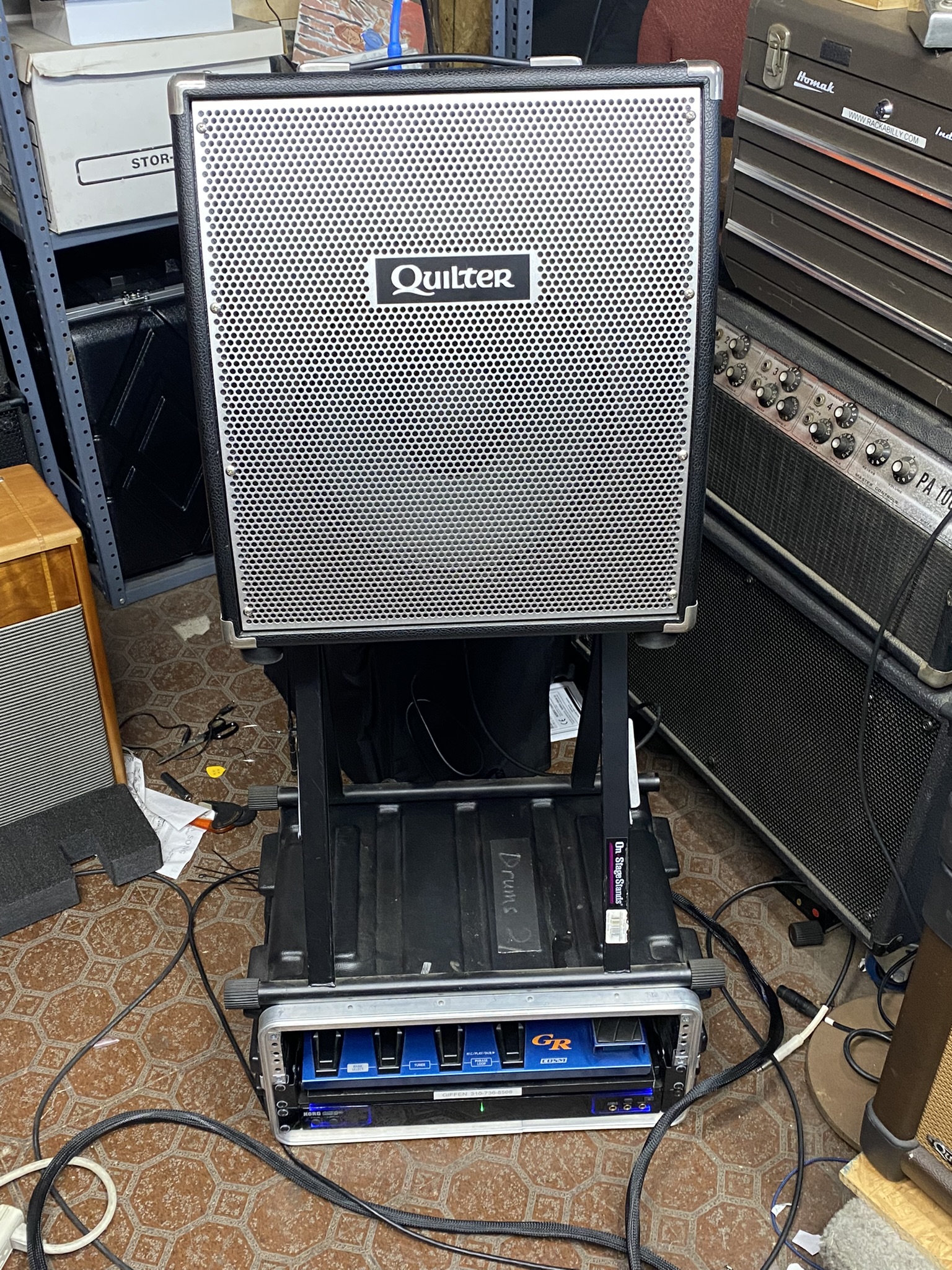
- The amp. I've been using a Quilter Mach 3 Combo amp lately, and it's a great amp for a lot of things, and it works well for most of the tones I use, but its boost adds some distortion, which is fine if you're playing an electric guitar, but when I'm modeling an acoustic guitar, its tone is less than ideal. The acoustic models tend to sound kind of thin, even on the cleanest setting, the "1965" voice. And having experimented with playing acoustic guitar through my bass amp, a Quilter BassBlock 802, I knew it could make acousticky things sound good, so I tried the rig through that amp with a Bass BlockDock 12 cab, and...we have a winner! Its 4-band EQ not only works for getting great bass tone, it fairly easily dials in a guitar/amp/etc. modeler (or two) like I use.
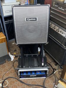 It didn't take long to realize that putting it up on this big stand wasn't going to work out well on stage, so now it just sits on top of the rack case with a little AmpWedge to tilt it back so I can hear it better. Really, though, with its 800-watt power section, pretty much everyone will hear it. Honorable mention goes to the Quilter MicroPro Mach 2 head, plugged into this cabinet, it sounds durn fine, too. But wait, there's more! I have another amp in the pipeliine, a tube amp that should sound pretty sweet, once I get it. Stay tuned for that.
As usual, the thing that astounded me most was that when I plugged it all in and tested it, it worked! Just like I wanted it to.
I took it out for a test run at this weekend's gigs (there were 3 of them), and it worked well, though it pointed up a few things I needed to tweak, which I did today:
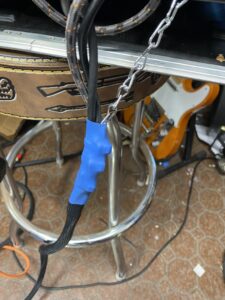
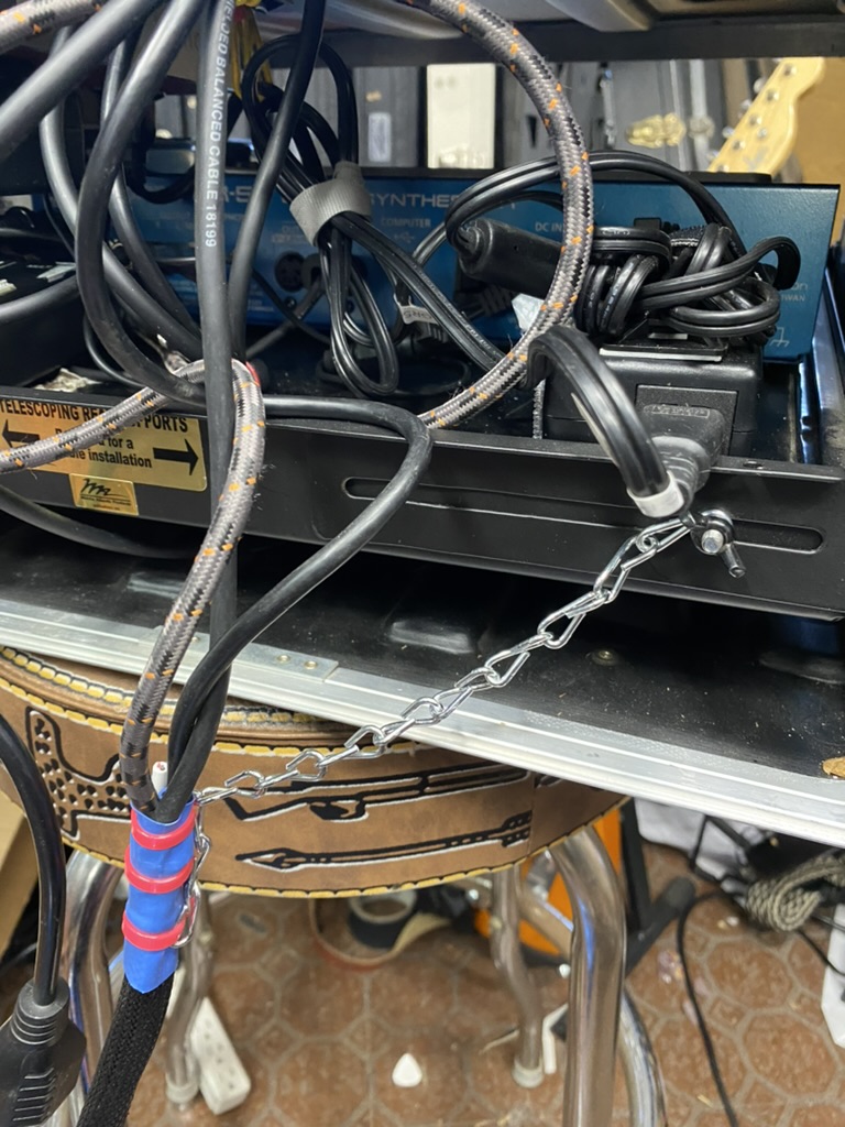
- I used another wire in the snake as a strain relief to protect the cable connectors and the things they plug into in the rack, but a little moving around, setting up and then packing up a few times, and the wire gave up the ghost. So I used a chain, zip-tied around the cable sheath, and attached it to the slideout shelf bracket, to protect the cable. I covered it in heat-shrink tubing to keep the chain and zip-ties in the right place.

- The Roland US-20 pedal is supposed to select either the SY-1000 or the GR-55, depending upon whether you select A or B, respectively, and any other time I've used this pedal with two different Roland devices, that's how it worked. But in this configuration, for reasons I still don't understand, it got finicky. I'd select A, and it would send out audio from B, or A and B. If I stepped on the A-B pedal a few times, it might work like I want, but I couldn't depend upon it.
- The SY-1000 has a great feature that sends MIDI messages from footswitches or expression pedals so you can control other devices from the SY-1000. Which is all well and good, but while it's sending a Control Change (like a volume adjustment) to the GR-55, it's also sending that adjustment to the SY-1000, and with the US-20 working the way it was, I ended up hearing both devices, when I only wanted to hear one. I'd been using a Boss LS-2 LIne Selector pedal to combine the two outputs from the two devices, but I couldn't get the US-20 to consistently silence the device I wasn't using, I was getting audio from both devices, and if one of them was in a different tuning, well, bad things happened. Also, the only place on the Pedaltrain board where the US-20 would fit made it inconvenient (i.e., hard to hit with my foot). The repurposed loop switcher (I haven't thought of a new name of it, maybe the Output Selector) took care of that, only one audio signal can go to the amp at a time, so the US-20 is permanently set to "Both" and everything works like it should. Would've been nice to not have to limit myself to that, but I don't have any songs I perform that need both devices at once, so it's not a big loss, especially given the reduced stress of knowing I'll get the output I need. And being able to control it via MIDI using the Voodoo Labs Control Switcher makes it easy to manage. And I'm only using one of the Control Switcher's switches, so if I think of something else to control, I can do it via MIDI.
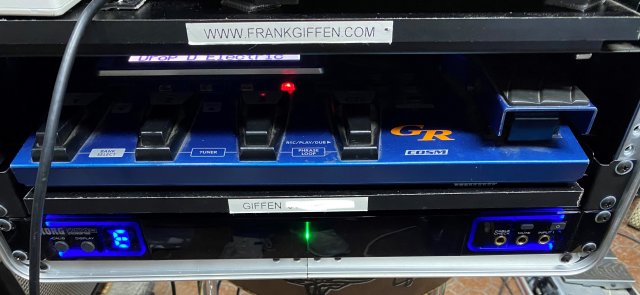
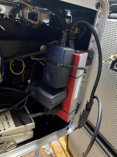
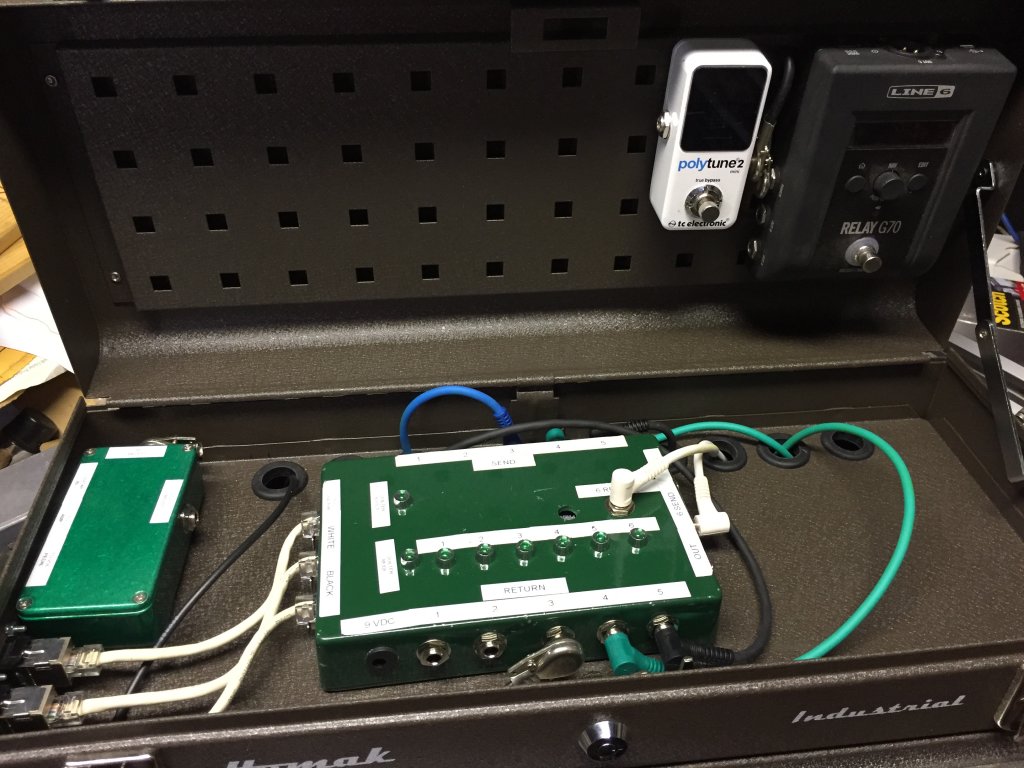
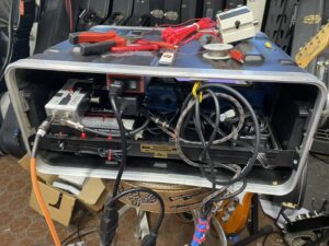 In this view, it's a little messy, I shot the pic as I was finishing things up, some of the mess can't be avoided because the MIDI, GK, and audio cables are slightly different lengths, and I need to give them enough slack to allow the drawer to pull out, but not too much so that they impede the drawer from closing; that's why they're suspended with hair elastics; the Output Selector is on the left, Dual Locked to the Control Switcher, which is Dual Locked to the drawer shelf; the power supply for the GR-55 is Dual Locked to the shelf on the right side. The Roland power supply provides more than enough current to power the Control Switcher and the Output Selector. The Korg tuner has its own power supply, which is plugged into the roof-mounted surge protector with the plug to the Roland power supply. I might have to zip-tie that little power brick into the surge protector, because it tended to fall out when I hauled it around this past weekend). I bought the Korg tuner used from Guitar Center, and it gets a little flaky sometimes. It always powers up, and it usually works, but sometimes it just sits there and doesn't hear the string I'm playing, so it doesn't do me any good. But it looks cool when it does work. I ordered a new one from Sweetwater months ago to replace it, but it was backordered for months, and they finally just canceled the order. Korg has a newer version out, but nobody has any in stock anymore. Now that I have the SY-1000 on the floor in front of me, I can use that tuner. Or I guess I could spend $30 on a Snark.

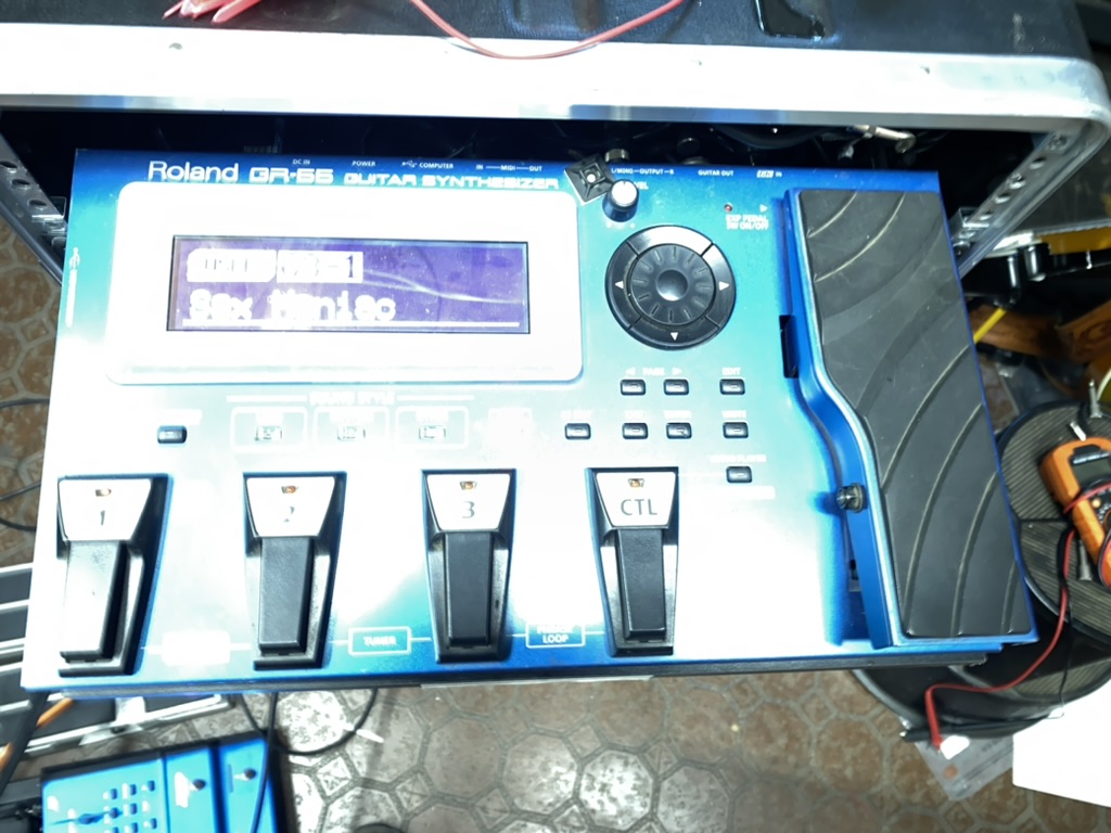
Not the greatest photo, but lighting conditions in my studio aren't great for photography at this angle. This just shows the GR-55 on its shelf, slid out of the rack. - I relocated and reprogrammed some presets on the Morningstar MC8 to simplify switching back and forth between synth sounds and regular guitar sound.

Although the hardware is all set up the way it needs to be, I still need to test all the MIDI commands I have programmed for each song in OnSong to make sure they bring up the right song, the right synth patch, and switch to the right output for it. That's a bunch of songs, so it may take me a little time. Until next time, rock on!
June 13th, 2022 -- More New Stuff
After the Rackette, I built a scaled-down version I called the Cowboy Board, because it gave me most everything I needed for Country gigs except a true synth sound for the intro to "Copperhead Road," the piano intro to "Seminole Wind," the flute part for "Can't You See" (there's a whole story about that song I'll have to relate one day), or the steel drum/marimba combo for "Margaritaville" (gratuitous but fun, even now), but the Boss GP-10 was giving me issues, and I thought that maybe something less than 10 years old might be viable. Again, I looked at things like Headrush and Line 6's Helix, but it came down to "do they allow me to change tunings on the fly on the guitar I already have?" and the answer was still "No." So that left me within the realm of Roland/Boss hex pickups and devices that worked therewith. Which quickly narrowed down to the Boss SY-1000 guitar synthesizer/processor. It does a lot. A helluva lot. But my needs are limited to different sounding guitars (acoustic or electric), different tunings (Drop D, Open E, D tuning (down a half-step), F tuning (up a half-step), 12-strings, baritone (C baritone) tuning, and Bass VI (down an octave). And some clean, distorted, delayed, overdriven sounds, plus a few others for unusual sounds. The SY-1000 does all that. So I bought one (it'll be paid for soon, honest!). Now, what to do with it, and how to control it?
The SY-1000 has something the GP-10 didn't: a direct MIDI interface, something I've come to depend on the last few years. With MIDI Program and Control Changes, I can pull up the right patch (preset) and adjust it as needed for each song. And there are plenty of ways to tell the SY-1000 what to do via MIDI. But how do I do that efficiently? And what do I use to send those MIDI streams to it?
The OnSong app on my iPad does a fairly good job of that (I used to say "perfect," but the latest version's MIDI implementation is a little buggy, to put it mildly, and I've been trying to optimize it for my purposes), but what about mid-song changes, like turning on the boost, changing overdrive types, changing tunings, or whatever? I bought a Morningstar MC-8 MIDI controller to facilitate that, and added 4 Boss FS-7 pedals, and 2 Nektar expression pedals to give me as full a control over the SY-1000 as is allowed. The MC-8 has 8 stomp switches you can program any way you like, and it's also got 4 TRS jacks you can configure to do most anything: dual footswitches, an expression pedal, even a MIDI Out interface). I opted to use the FS-7s to turn different things on and off. The SY-1000's FX1, FX2, and/or FX3, the distortion type, the compressor on/off, the EQ on/off, and the Noise Suppressor on/off, and a "panic button" that zeroes out the volume in case things get unduly squirrely. Stepping on it a second time puts the volume back, at halfway up (100 of 200 in Boss terms, CC64 in MIDI terms). Plus some things like switching between two different distortion types. The two expression pedals are cabled directly to the two jacks for them on the SY-1000. One serves as a volume pedal, the other as an expression pedal as defined in the patch, usually as the wah or pedal bend pedal. As for the Morningstar's 8 native switches, I use them for Alt Tuning on/off, Alt Tuning Type (patch dependent), Chorus on/off, Distortion on/off, Delay on/off, Boost (amp solo switch) on/off, plus 2 buttons for controlling OnSong on my iPad, one to scroll up and one to scroll down.
But having all this control comes at a price in terms of real estate. I wanted to have everything on one board, but the only pedalboard that accommodates that is a Pedaltrain Pro, a massive piece of aluminum that doesn't fit on many of the stages I play on. And I have one of those, I even have a flight case to carry it around in (it's even got wheels!), but I can't bring myself to do that to either myself of bandmates. So I used a "Divide and Conquer" strategy by using two pedalboards, a Pedaltrain Classic 2 and a Pedaltrain Metro 20. The SY-1000, the Morningstar MC-8, the Voodoo Labs Pedal Power 2 Plus power supply, a MIDI Solutions MIDI Merger, and the absolutely-required Atomic Brain sit on the Classic 2, and the two expression pedals and 4 FS-7s reside on the Metro. This, somewhat regrettably, requires no fewer than 7 cables to connect the Metro to the Classic: 4 TRS cables for the FS-7s, the 2 cables on the expression pedals, and a long 2.1mm power cable to run 9VDC back to the FS-7s from the Pedal Power Plus. So I made a snake that sheathes those cables and keeps them somewhat organized (it only helps so much), the snake slithers (yeah, I had to use that term) under the Classic and comes up in the middle, so everything plugs in as conveniently as possible. I might be able to redo this with 2 CAT5 cables and make a less bulky snake, but I'm not sure it'll make things that much easier. But I haven't ruled it out. All that said, it sounds great with the Quilter Mach 3 amp I recently acquired.
The downside to the new gear is that using it requires programming every song in my OnSong library to send it the correct Program and Control Changes when I call the song up. I've just finished doing that, and the first gig with this rig with Pull The Trigger is this weekend, so we'll see how it goes.
March 30, 2022 -- New Stuff All Around
Not much in the way of new gear, though I do have a new Reverend Flatroc RB. The RetroBlast pickups have become my favorite new pickup. They don't hum, yet they can twang, and in a Reverend guitar (the only place you'll find them), they can really twang when you fiddle with the bass contour control. And the Flatroc RB comes with a Bigsby, which makes it a real guitar, so there's that. Really happy with it so far, and looking forward to playing it in more gigs with a new band I started playing with.
Honestly, Pull The Trigger isn't a new band, they've been around about 10 years. And I actually played with them for the first time over 2 years ago. And we like each other enough that they booked me for a bunch of more gigs in 2020, and we all know where all the gigs went in 2020. Luckily, I was able to reconnect with them late last year, and it's like we picked up where we left off. The two founding members of the band, bandleader Greg Mercado, and bassist/chick magnet Ed Wada, are fun to work with, and their curated set list is chock full of Merle and Waylon songs, plus lots of other good tunes. Their latest drummer, Richard Carrillo, is a talented guy and the four of us are making good noises and pleasing crowds. And sometimes Greg ropes in another guitar player (because you can never have too many of those), and we put on quite a show. But really, my favorite part about playing with these guys is, they're based in Ventura County, and I love going back to the homeland to play there. And we go a little north, to Maverick's in Santa Ynez, those gigs have been great fun, along with all the times we've played at The Shores in Oxnard. Come on out whenever we're there, we do not disappoint.
The Rackette pedalboard/rack system has been working out pretty well, but I keep messing with it, and honestly, for most gigs, I don't need the synthesizer. So I'm going to work on cleaning up the cable routing and put it on hiatus for a while. But I do like the "quick-change" capabilities of the GP-10, which I guess is why I have two of them, and I put the other one on my "Cowboy Board" pedalboard, and I'm going to use that board a lot. It works for Lizards gigs, it works with the Boilermakers, and it works with Country gigs (where the board got its name). I recently bought a second Primova MIDX2 MIDI interface for the GP-10 and put it on the Cowboy Board, and that, coupled with the Yamaha Bluetooth MIDI adapter, makes it easy to bend the GP-10 to my will with the iPad, without any pesky cables. Gonna try out the latest iteration of the Cowboy Board at this weekend's gig with the Leapin' Lizards. The Lizards are starting to book more gigs for the remainder of the Spring and for the Summer, so come on out if you see we're somewhere you can attend.
December 31, 2021 -- Year-End Project
A New Pedalboard Contraption - The Rackette - Gig Versatility Without the Backache
A couple years ago I had the idea of maximizing the number of crazy sounds I can produce with a guitar yet still be able to gig with it, and at the same time make use of all, or at least some, of the gear I already own. For Country gigs, I use a lot of different sounds, a lot of different tunings, and I need to jump from one to the other quickly. So I concluded the best way to do that was with a Roland VG-99, the 12-year-old Future of Guitar (“The Future of Guitar” is how Roland described it when it came out), because it can do pretty much anything, except transport easily. Mine’s getting old, and if and when it breaks, it’s going to be all over. But I did it anyway. And for anything the 99 couldn’t do (like steel drums for “Margaritaville,” and that zany synth tone for “Copperhead Road”), well I already have a Roland GR-55. And I thought, while I was at it, I’d get into something a little more modern, like BiasFX, so why not put a laptop in the rig, with an interface, and then control the whole mess with a MIDI foot controller, ah, I’ve already got an FC-300, that’ll work. And get the audio under control with a MIDI-controlled mixer. And I’ve got an extra Furman power conditioner, so yeah, let’s use that! Put it in a rack, say, 10U, oops, gotta be 12U to fit. And it all worked, and I nicknamed it Count Rackula, which I later learned was a name used by a hip-hop artist, but it (the rack, I don’t know about the hip-hop artist) was kinda big to take to a bar gig, and no fun to lift when there wasn’t a ramp up to the stage (just ask Will Tone, who injured his back when I asked him to help me load it into the van one night). So I started in ta thinkin.’
Honestly, I never used the BiasFX rig, at least, not in the Rackula. And did I really need a power conditioner for a pedalboard? No. And there had to be easier ways to control the audio paths of the two devices I did use, so let’s take the mixer out of the equation. How small can I make that? The answer was 6U’s worth of rack space. I can get a rolling case with a built-in handle that’s much smaller and much easier to lift, and can put the Quilter MicroPro on top of it so it looks a little more like a normal guitar rig. Still using the FC-300 with some additional stomp switches, and the iPad will still use OnSong to control it. Again, crazy? Yes, but it just…might…work!
I found a fairly lightweight but sturdy 6U rack case (it billed itself as a 5U, but that’s because it only has 5U’s worth usable full-depth space, the bottom U has the handle mechanism protruding up into its space, but more on how I dealt with that later). I started cannibalizing the Rackula case. I felt a little wistful at snipping all those zip ties I’d put into that, but I also thought “Zip ties are cheap, and I can re-do it if this doesn’t work out.” I pulled two of the sliding shelves out and put them into the case, one to hold the GR-55 synth, and one to hold the GP-10 and a few other things. 3Us for one, 2 for the other.
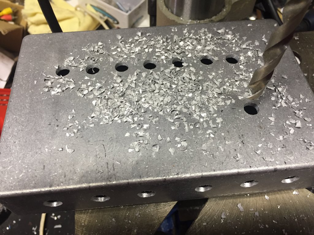
Something missing from the Rackula system, and I really missed it, was the Nocturne Atomic Brain pedal. So I put that on one of the shelves, behind the GP-10. This particular Brain (I have 3) is special, my wife actually owns it, having won it in a Gretsch Roundup raffle, and when that happened, Tavo (the guy who built the pedal) scoffed and said “You’ll probably just put Velcro on the bottom and stick it to a pedalboard,” I took that as a challenge and promised never to do that. I’ve zip-tied it to a board, I’ve let it flop around loose on a board, but up to that point, I’d never velcro’d (or Dual-Locked) it down. And I wasn’t going to start now. So I got ta thinkin’ again and recalled that I’d just changed the chain on my bicycle (one of them), and I had an old chain that wasn’t any good for bicycle usage anymore, so that made me recall how someone else said they fastened pedals down to a wooden pedalboard, by using bicycle chain links. A bike chain link looks like the number 8. Two holes and some metal around them. You take one screw out of the pedal case, put it through one of the holes in the chain link, and screw it back into the pedal. Do that 3 more times with the screws that hold the pedal together, and you've got 4 mounting tabs for the pedal. I had the chain, I had the chain breaker, the shelves I’m using are wood, I had some degreaser, I had some wood screws, hmmm, like Yogi Barra used to say, “Necessity is a mother of an invention,” or something like that. And now the Brain is secured to the shelf, and no Velcro was used. Promise kept.
But adding this to the equation meant solving said equation got a little more complicated. Why? Because I don’t always use the Brain in my tone (gasp!). There are some applications, like synth tones, and some modeled acoustic tones, that sound better without it, for some reason. How to deal with that? Well that’s easy, step on the bypass switch. But what if the pedal is screwed down to a shelf and ensconced in a rack? OK, that’s a little more complicated. I needed a loop switcher, and it has to only switch one device, and it has to be small enough to shoehorn into this little rack I’ve confined myself to. Does one exist? No, gonna have to invent it. I have some audio-grade relays around here somewhere that I used for the Rackabilly project, but Lord knows where they are (I’ll probably find them soon), so I ordered a few more (in case I ruin one in building this new contraption), and ordered the rest of the parts from LoveMySwitches.com (formerly known as BitchesLoveMySwitches.com). But I got impatient and started cleaning up my workbench while waiting for the rest of the components to arrive, and discovered that I had everything I needed to build this new thing, which I call either The Brain Bypasser, or just The Magic Box. A little drill press time, some perf board, and it was all built.
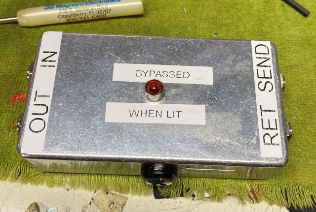
And I didn’t need to build a MIDI interface into it, because I already had a Voodoo Lab Control Switcher for switching amp functions on the Quilter amp I use. And I didn’t really need to switch 4 different amp functions, 3 was plenty, so I used one of the four controllable ports for the Magic Box, and CC95 now controls whether the Brain is in the loop or not.
Eliminating the mixer meant having to find a way to switch between the GP-10 and the GR-55 (I may need to use them simultaneously someday, but that need hasn’t arisen yet; when it does, my current solution will be compatible with it), but a little brute-force MIDI configuration took care of that. As an aside, the Boss GP-10 works with MIDI via USB, but isn’t a class-compliant USB MIDI implementation, so that’s not much help. But a company in Scandinavia called Primova Sound fixes that, with a little box called the MIDX-2 (he makes some other cool stuff, and another of his pedals is in use on this rig, and I’ll get to that later). The MIDX-2 has 2 standard 5-pin DIN MIDI ports (In and Out), and you plug a standard USB A-B cable between it and the GP-10, and you can send MIDI code to your GP-10 to control dozens of standard functions by default, and using the GP-10’s Control Assigns, you can add 8 more custom CC controls. It has even more functionality that I’m not even using (yet), so as you might guess, it’s one of my favorite devices. And it runs on 9 VDC or USB power, so powering it is easy. All this to say that muting the GP-10 is as simple as turning on its tuner, which mutes the audio output. So sending CC3 with a value of 64 or higher will quiet it real fast. And if I could see the tuner, I could tune as needed, but I can’t, so that’s a moot point. More on the tuning solution later.
Muting the GR-55 is a little more complicated. Though it has regular MIDI In and Out ports, it doesn’t (as far as I know; once I found a solution on vguitarforums.com, I went with that and stopped researching it) have a built-in CC that effectively mutes its audio. But using one of its 8 customizable Control Assigns, you can set one to do it by having it turn the tone switch for whatever sounds you’re using (up to 4) on and off with the same CC. That can eat up half of the available Control Assigns, but it makes for a reliable, easy-to-grasp (which is important for me) means of mute-age. The brute-force aspect of it comes from having to make sure any patch you’re going to use has those CCs programmed into it, and every patch on the FC-300, and (ugh, talk about tedious) every song in OnSong sends those CCs to keep things under control. Since the MIDX-2 uses CC3, I tried to keep a little sanity and use that CC for the Control Assigns on the GR-55 (the GP-10 is on one MIDI channel and the GR-55 is on another to keep things separate).
I started this discussion with the noisemakers, a.k.a., the signal processors that produce the sounds, but that’s kind of starting in the middle of the signal chain. Stuff has to get into these devices, and it has to go somewhere when it comes out, so let’s talk about that. First the “Ins.” My guitars (well, a number of them) have either Roland GK-3 or a piezo-based hexaphonic (a.k.a., “synth”) pickup. I’ve got two GraphTech GHOST systems on two Tele partscasters I built, and one RMC that came standard equipment on my Godin Multiac Nylon SA. Those use the required 13-pin GK cable (I later learned that cable, or at least the connector, is a standard automotive connector used mostly outside the US) to get to the processors (what I’ll be calling the GP-10 and GR-55 from here on out), and to get to them simultaneously, I use a Roland US20, which is a $200 (or more) ABY switch for GK cables. I bought one when I first built my “Motherboard” pedal board (so named because it sat on a Pedaltrain Pro pedalboard which fits into a case large enough to hold a small- to medium-sized child, albeit a very thin one), then when I retired that board I put the US20 somewhere and couldn’t find it when I needed it again and bought another, then of course, immediately found the original one. Anyway, I mounted the US20 on the shelf with the GP-10 (the only place it would fit) and keep it in “Y” mode so the magical electrons are always being sent to both processors. Whether the device gets heard or not depends upon how the mutes are switched (see above paragraph), but it doesn’t cost any more to run them on all the time, so that keeps things (relatively) simple. But of course, this can’t be simple, otherwise it wouldn’t be a Roland product collection. Those piezo synth pickups work fairly well on the GP-10, but can get a little squirrely with the GR-55. To remediate this, the gentleman at Primova Sound makes a SubSonic filter that cleans up the signal going into the 55. But wait, there’s more! It also has a ¼” input, so you can conveniently plug a regular guitar pickup into your GK-based system and play it, too. There’s an analog effects loop so you can include outboard analog effects into your signal, and ¼” switch inputs so you can externally trigger the S1 and S2 buttons on the GK pickup. I use the analog input, but I’ve never used the other functions. So the cable from the guitar goes into the subsonic filter, then into the US20, then on through the rest of it.
Now for the “Outs.” Each processor has a stereo out capability, but this is enough to carry around without needing two amps, so I just take a mono out from each box (it’s the Left channel, for the record). Now I’ve got to take those two and feed them into one input to the amp. So I use a Boss LS-2 Line Selector, a multifunction switcher/mixer, and I use it in A/B/Mix mode, adjusting the levels of each so they’re as close to the same as possible, and feed the one output to…no, not the amp. On a normal pedalboard, it would go to the Atomic Brain and then to the amp, but since I can’t stomp on the Brain (sounds messy, anyway), the signal comes out of the LS-2, into the Brain Bypasser/Magic Box, out to the Brain, back into the Magic Box, and finally out to the amp. Still with me? Good.
A Few Odds and Ends That Make This Work:
The Roland FC-300 foot controller.
I’m using one of these that I’ve had for a dozen years or so (and it looks it, but it still works!) in Patch Mode, wherein up to 100 patches can be called up, a MIDI stream gets sent when the patch is activated, up to 8 different CC messages can be sent for each patch via 2 internal stomp switches and up to 6 external ones (I use 3 Boss FS-7s to get 6 switches in as small a space as possible), and two expression pedals for variable MIDI controls like volume and crossfades (for one patch I use it as a digital B-bender). Another couple of CCs are available via the switches under the expression pedals; I use one for turning the Wah on and off, and the one under the volume pedal acts as a panic button to mute the patch.
The FC-300 is the centralized point of origin for all the MIDI messages that control the other stuff. When I built the Rackula system, I needed a way to send MIDI commands from both my iPad (via OnSong) and from the FC back to the rack. To do that, I put a MIDI Solutions Merger V2 2x2 MIDI Merger (with 2 ins and 2 outs) down next to the FC-300 and plugged a USB-C to MIDI interface from the iPad into one In and one Out of the Merger. The FC-300 MIDI Out was plugged into the other In on the Merger, and a cable from the Merger’s other Out port went to a MIDI Solutions Quadra Thru MIDI Thru box with one In and 4 Outs attached to the front of the big rack to facilitate plugging it in. In using it that way, I made a discovery or two: 1) plugging the MIDI cable into the front of the unit is convenient for plugging in, but I kept tripping over the MIDI cable over the course of a gig, something I could have avoided if it went around the back, and a 20-foot cable was plenty long enough for that. In the course of this project, that cable broke 2 leads inside it somewhere, so I had to replace it. All that stepping-on may not have caused the cable to fail, but it didn’t help. 2) the connection from the iPad to the FC-300 required that my iPad always be close to the FC-300, and that means always having to use a mic stand iPad holder or a music stand. On my other pedalboard, I used the GP10 with a Yamaha MD-BT01 Bluetooth MIDI adapter and my iPad talked to it wirelessly. I wanted to do the same for this system, but wasn’t sure how this was going to work. For one thing, how would it plug in? My first thought was, “just like the cable from the iPad did, the Out to the In, and the In to the Out.” Except the connectors wouldn’t reach. Soooooo, well, how about a 1-foot MIDI extension cable?, Amazon has those. And yup, it worked. I zip-tied everything to the MIDI Merger and Dual-Locked it to the front side of the FC-300, and it looked nice and neat. Until I accidentally kicked it a couple times trying to step over it, the good news is, it all still works. The bad news is, it doesn’t look as neat anymore.
The MIDI Solutions Quadra Thru is now on the back of the 6U rolling rack case, securely zip-tied to the rack rails on the back of the case. The (new) 20-ft. MIDI cable plugs in securely there. This picgture shows it securely zip-tied to the side of the rack case. The CAT5 jack is piggybacking on top of it, and will be described below.
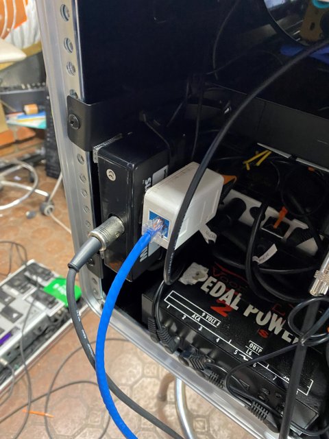
I mentioned the Voodoo Lab Control Switcher, it’s a MIDI-controlled 4-port bank of on/off switches that can be turned on or off with 4 different CC messages (one each). I have 3 of them controlling 3 functions on the Quilter MicroPro amp (mode, a.k.a., channel switching, boost, and tremolo) and the 4th one is for the Brain Bypass. The Control Switcher is Dual-Locked onto the back rail of the upper slide-out drawer. The Brain Bypass is Dual-Locked piggyback-style onto the back of the Control Switcher. The Control Switcher’s controlling outputs are 4 ¼” jacks, and a 5-pin DIN connector. Neither of these works with the Quilter’s RJ-45 jack directly, so I built, as Johnny Cash said in his song “One Piece At A Time,” an A-dapter kit using a surface-mount CAT5 jack (see picture above). I drilled a big hole in the back of it and mounted a DIN jack there, then wired the appropriate leads (details available on the Quilter Labs website) to the pins of the CAT5 side, then I can use any CAT5/5e/6 cable to connect to the amp. That A-dapter kit is Dual-Locked piggyback style to the top of the MIDI Quadra-Thru box.
Both the GP-10 and GR-55 have built-in tuners, but when they’re sitting on their shelves nestled into the rack, you can’t see them, so they’re not much good. On the Rackula, I put a little Boss TU3 mini on the front next to the mixer, and put it on upside-down so it would angle up a little for easier viewing, albeit in reverse, so left is sharp and right is flat, which my dyslexia helped me cope with. But I never really liked it all that much, and on an outdoor gig in daylight, it was pretty useless. This new rack case is 6U tall, but only the top 5U is usable, though there’s a little depth on the bottom U. I thought if I could find a very shallow-depth rack-mount tuner, that would be darn near perfect. And it so happens that the newest Korg tuner, the PB-05 PItchblack Pro, fits just perfectly there. I even found one used but excellent condition at GC for about $35 less than new one. Problem solved, well, I think it is, I haven’t had a sunny day lately to go outside with it and try it.
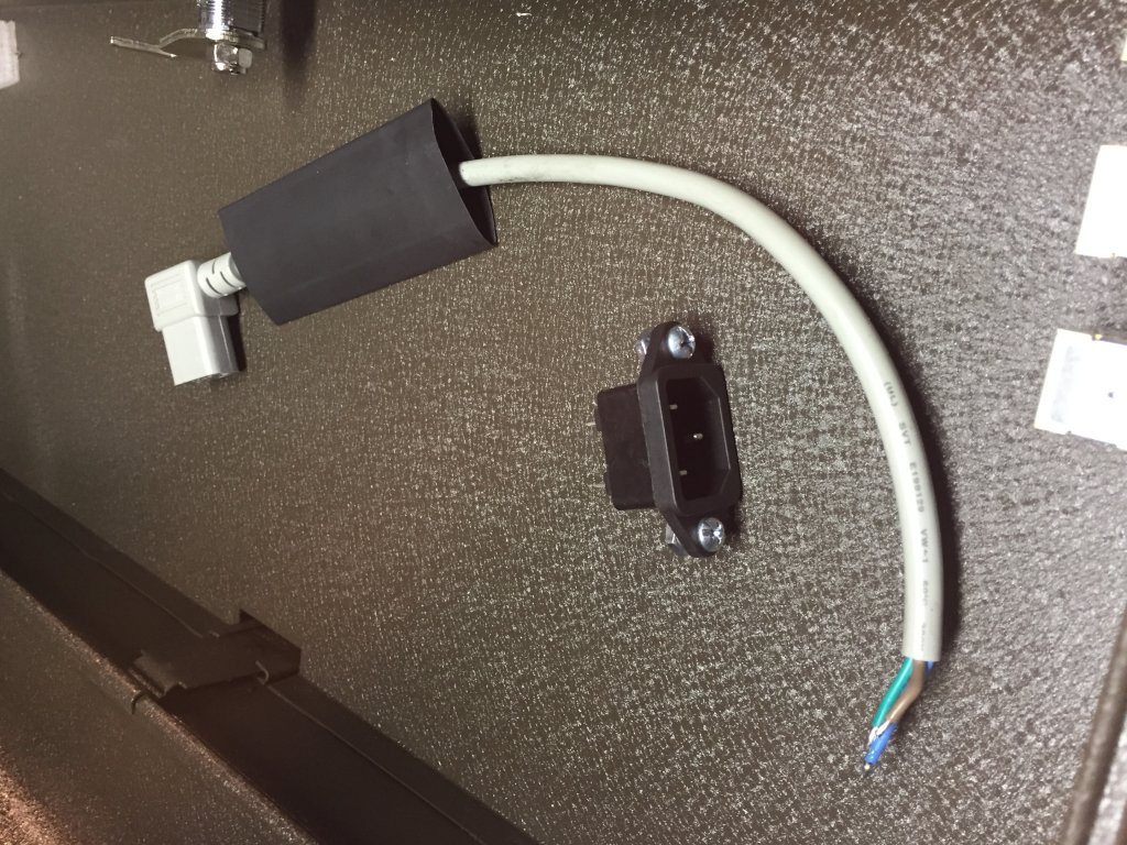
No large-scale project is complete without a power struggle of some sort. Since I was the only one (crazy enough to be) working on this, I had no one to argue with, so I had to settle for a device power struggle. Yeah, I know, a long way to go for a pun. Anyway, let’s go over what needs power: The GP-10, the GR-55, the Korg tuner, the Control Switcher, the Brain Bypass, the MIDX2, and the Atomic Brain. And every one of them runs on 9 volts. Simple, right? Eh, not so much. The current demands of the 55 preclude it from using even the high-current outputs of any Voodoo Lab Pedal Power supply I have. And the GP-10 will work on one of the high-current port, but it’s pushing its limits. Then the Korg tuner is 9 volts, but the polarity is different on the plug, and the plug’s a different size. I saw opinions online on both sides of the argument of whether it's safe to use a polarity-reverse cable or cutting up the one on the Korg without blowing it up, and decided to err on the side of caution and use the Korg’s included AC adapter. I did use a Pedal Power 2 Plus to run the Atomic Brain, the MIDX2, the Control Switcher, and the Brain Bypass. So that means 4 AC plugs. And the only power strip I have that will fit in that case has 3 outlets. Fortunately, the Pedal Power has a convenience outlet on the back, and in this case, that was very convenient. It all plugs into the power strip, a JouleBAR in Apple Red. I bought this power strip at a NAMM Show as an impulse purchase and carried it to every gig in its velour bag, but never used it. It has some nice features, like a detachable IEC cord, which turned out to be a godsend because I use an IEC/NEMA splitter Y cable to provide an electrical outlet to plug the amp into. And the IEC inlet on the strip is a little difficult to get to, so I just leave the Y cable in the power strip and plug another IEC cable into it. In taking it out on its maiden voyage, I discovered the wall warts don’t stay plugged in during transit, so now they’re zip-tied down. Haven’t taken it anywhere but up and down the driveway just yet, but so far, they’re holding.
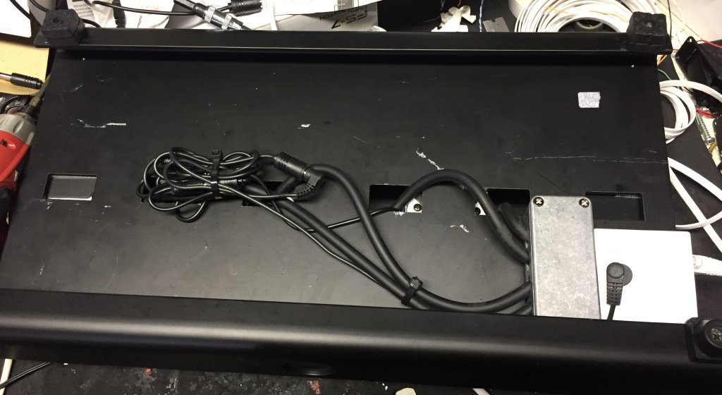
And speaking of holding, there’s something you don’t have to deal with on a standard pedalboard that becomes very important when you start putting things on slideout drawers: cable routing. On a typical server rack, equipment that slides in and out on rails or drawer glides has folding hinged cable channels that keep the cables out of harm’s way. And that’s fine on a 7-foot rack cabinet that sits stationary in a server room, where all the cables connect at the same place, i.e., the back of the equipment. Trying to adapt that concept to the disparate-shaped and sized components with connections in different locations on a rolling rack case with the limited space I’m dealing with here proved a little too daunting for a standard approach, so like with most crazy ideas I get, I had to improvise. My experience with the Rackula project was that cables caused fewer issues if they were suspended as much as possible over the devices they connected to. And they're less likely to go where they're not suppoed to if they're in sheathing like this. So I used longish cables to allow the fullest extension of the drawers, and this time, I used small hair elastics (“Goody” brand) and zip-tied them to stick-on mounting pads to suspend them over the components. Depending upon the amount of needed elasticity, I mounted them a couple of ways, as shown in the pictures.

On the shelves themselves, I screwed the mounting pads down and zip tied the cables to them to keep the cables from pulling out of their jacks. And there was a lot of trial-and-error, and successive issue resolution until all the cables stayed reliably out of where the sliding shelves were supposed to go. It doesn’t look as neat as it possibly could, but if I can figure out a better way to do it, or if new issues arise in practical application, I’ll implement that.
Between the sheathing and the hair ties, I managed to route the cables in a way that worked. So essentially, I spent half the day getting the shelves to do this:
Tone Suck? I Think Not
The guitar’s signal, especially the analog signal, goes through a subsonic filter, gets split into two signals and fed to the two processors, then comes out and merged through the LS-2, out through the Brain Bypass, through the Atomic Brain (or not), and (finally) out to the amp. With such a circuitous path, I fully expected the tone to suck. But it doesn’t! Is there a little signal degradation? Yes. Does it negate the advantages of this rig? No! I think between the signal buffering of the processors and the Atomic Brain, it comes out pretty nice. I don’t know whether I base my ideas in reality so they’re more likely to turn out well or if I just keep getting lucky when I do these things, but either way, I’ll take it.
Seriously contemplating some LED strip lights to put around the perimeter of the rack space. I switched a port on the Pedal Power to 12V so make it work. If it happens, I'll let you know.
September 12, 2017 -- Summer Guitar Build
I don't know why I feel the need to have a summer guitar build project. I have plenty of other things to do, and plenty of other guitars to play. But that doesn't stop me. In this case, I had a Tele neck I'd special ordered, and I had a request from a friend to try out some new pickups he'd created. And I didn't want to carve up one of my Reverends, so I thought I'd take care of everything with a build. And I do mean everything. I decided to add a Strat tremolo in a Tele-sized guitar, and put in a Ghost piezo/synth pickup system so I could use the guitar with either the Lizards or with Sterling's band.
And I almost made a liar out of myself, because I almost didn't get it done during the summer. But I brought it in under, or at, the wire, and here we are.
From the start, I had said this would be my summer build project, even though I first bought the body in February. And I almost didn’t get it done by summer’s end. And technically, it’s not quite done, as one switch and one concentric pot need to be replaced, but it is a functioning guitar, so that’s close enough for me.
A friend of mine named Mel Waldorf is a resourceful and multi-talented person. Not only does he lead Meshugga Beach Party, and has managed to appear on The Gong Show this year, he’s also an inventor, and now, he’s a pickup maker. Alameda pickups are his fiendishly brilliant creation, and he asked me to try a pair and see how I liked them. He can make them in any of several different form factors, and I chose standard humbucker-sized, to maximize the number of guitars I might put them in,
Now he had a couple of delays in getting the test pickups to me, but I managed to redefine the term “extended delays” in my efforts to create an instrument with which to test the pickups. Because it took a long time. A really long time.
The biggest delay was getting started. I had to travel a lot for my day job this year, so it was tough to be home long enough to get things arranged for the finishing process. Then my main band and a band I’ve been subbing with started playing out a lot more (yes, these are problems you like to have). Then I got some time and started on the Rackabilly project (see below), and owing to limited space on the bench, that had to get done before anything like a build could commence. But eventually I got started.
I wanted to build a Telecaster with humbucker-sized pickups, and use a Strat-type trem with it, and while I was at it, build in piezo/synth capabilities via a Graph Tech Ghost system. And I wanted it to be Cadillac Green. Well nobody makes a ready-made body like that, though Warmoth could get close, but that $199 or so they want to put the finish on seemed exorbitant (retrospective reflection: it’s not), so I thought I’d do it myself with ReRanch rattle cans. Won’t be doin’ that again. Not that there’s anything wrong with ReRanch, I just don’t have the correct physical environment (in other words, a backyard spray booth is not optimal for good finishing) to do this well. Nevertheless, I persisted.

Sealer,
![]()
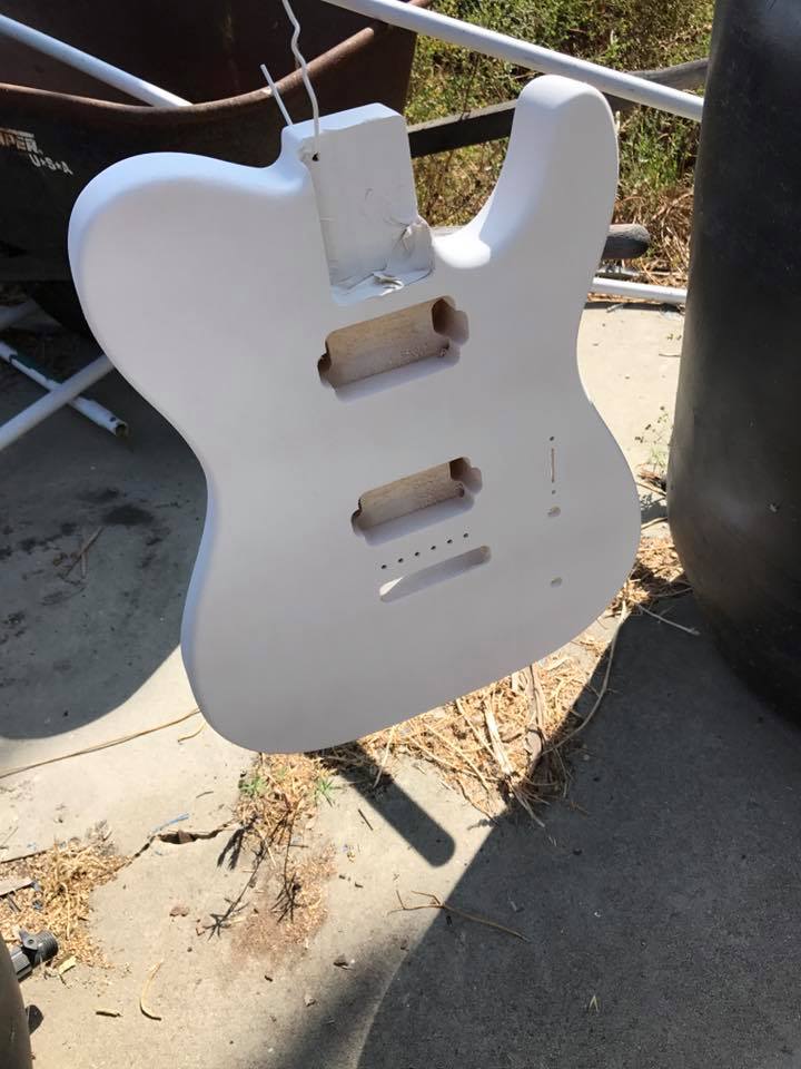
primer,
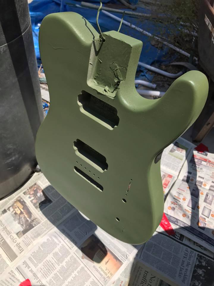
color coats,

clear coats,
and oh yeah, lots of dust and other particulate matter to make it a real ratrod-esque, “textured” finish. Not the answer I was lookin’ for, but it was the answer I got. I’m happy that parts of it look pretty good now that it’s buffed out. And parts of it don’t, but that’s my problem.
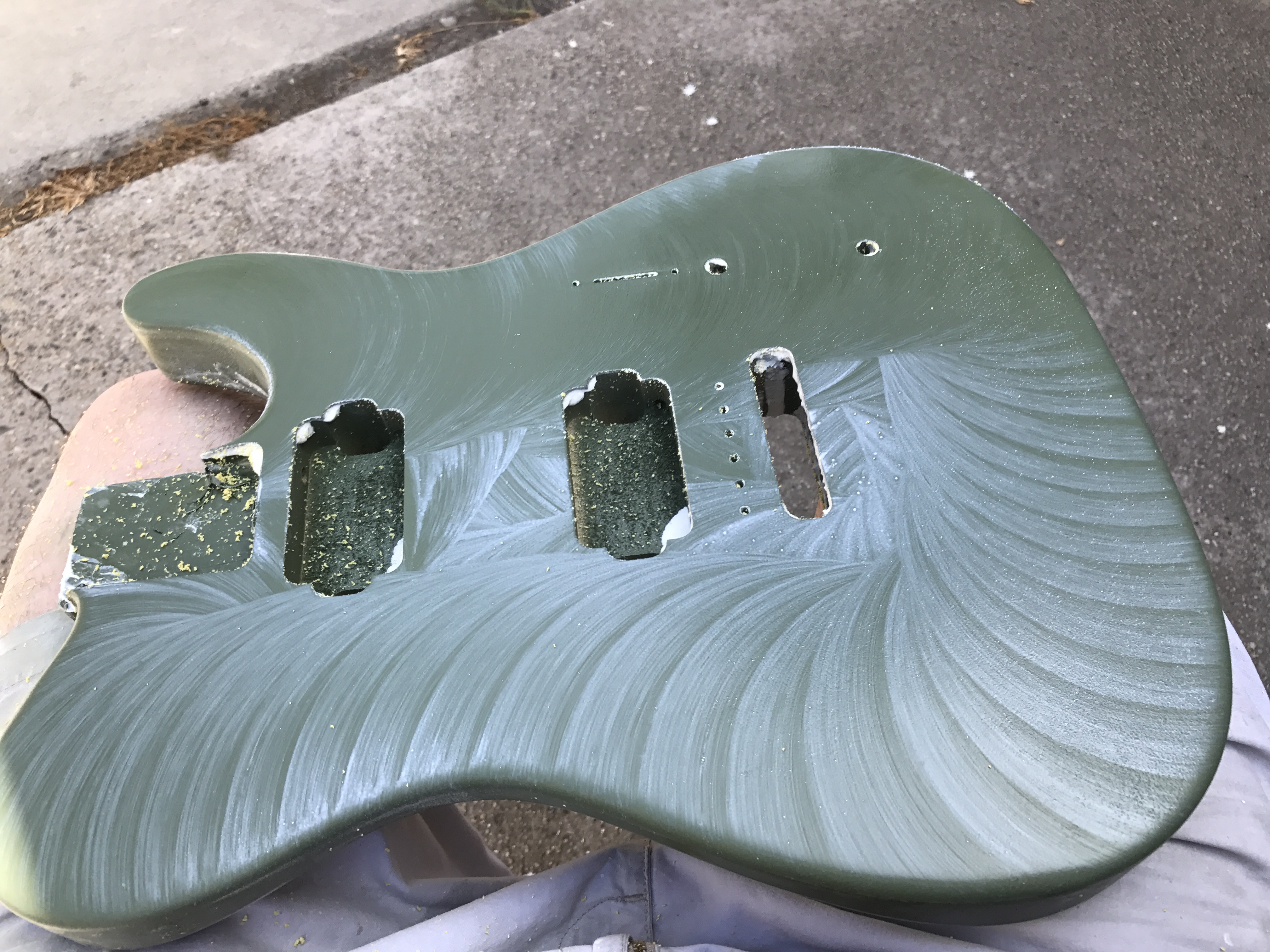
So, back to the build. All those coats needed to set a spell, the prescribed period was a week. Stuff came up, and it ended up being two weeks. Yes, I'm aware this picture is sideways, no, I don't know why.
![]()
Through a splattering of buffing compound, decomposing foam drill-mounted buffing pads, 1200 grit wet sandpaper, and a microfiber polishing cloth or two, and that body looked as good as it was going to.
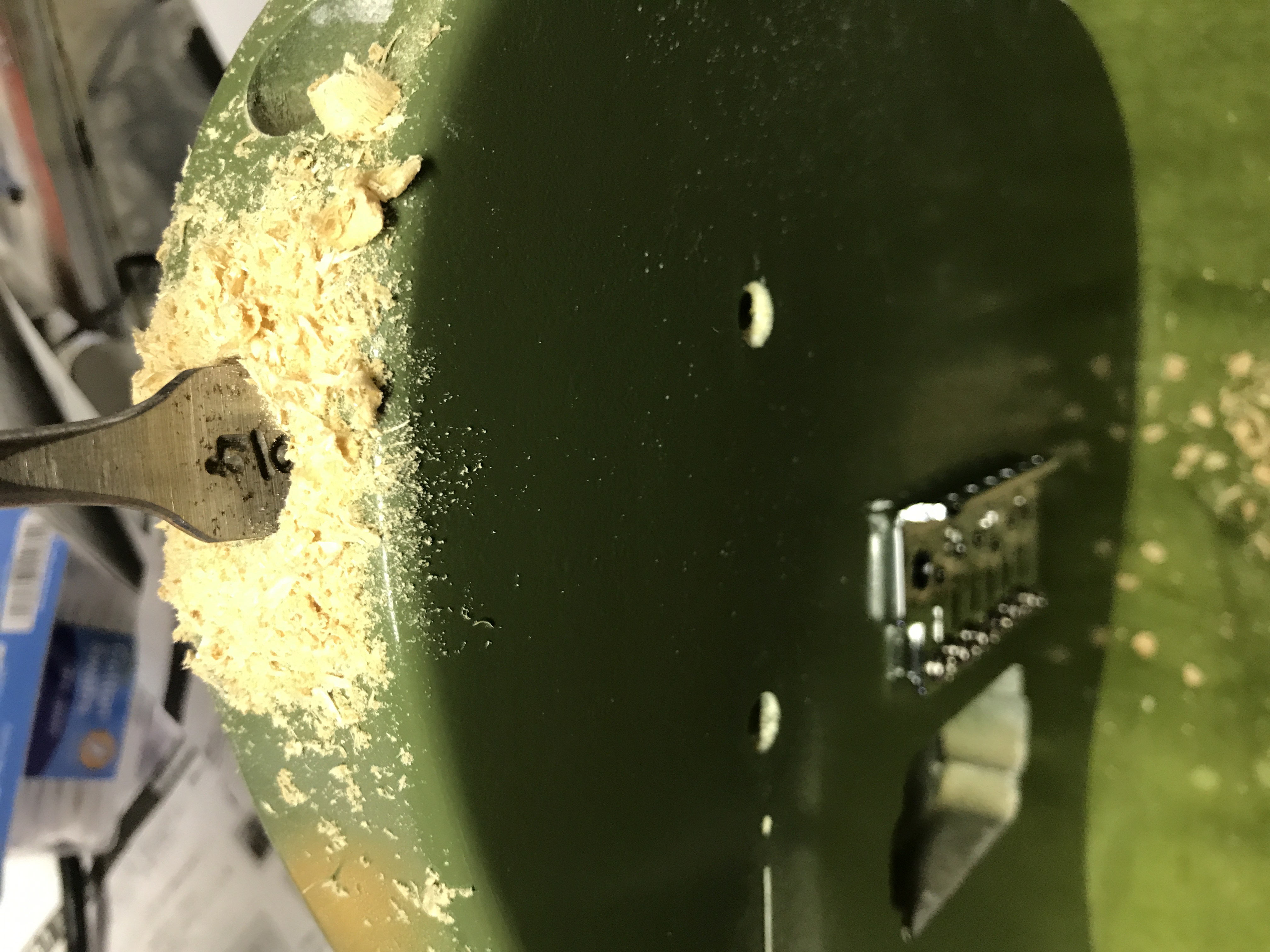
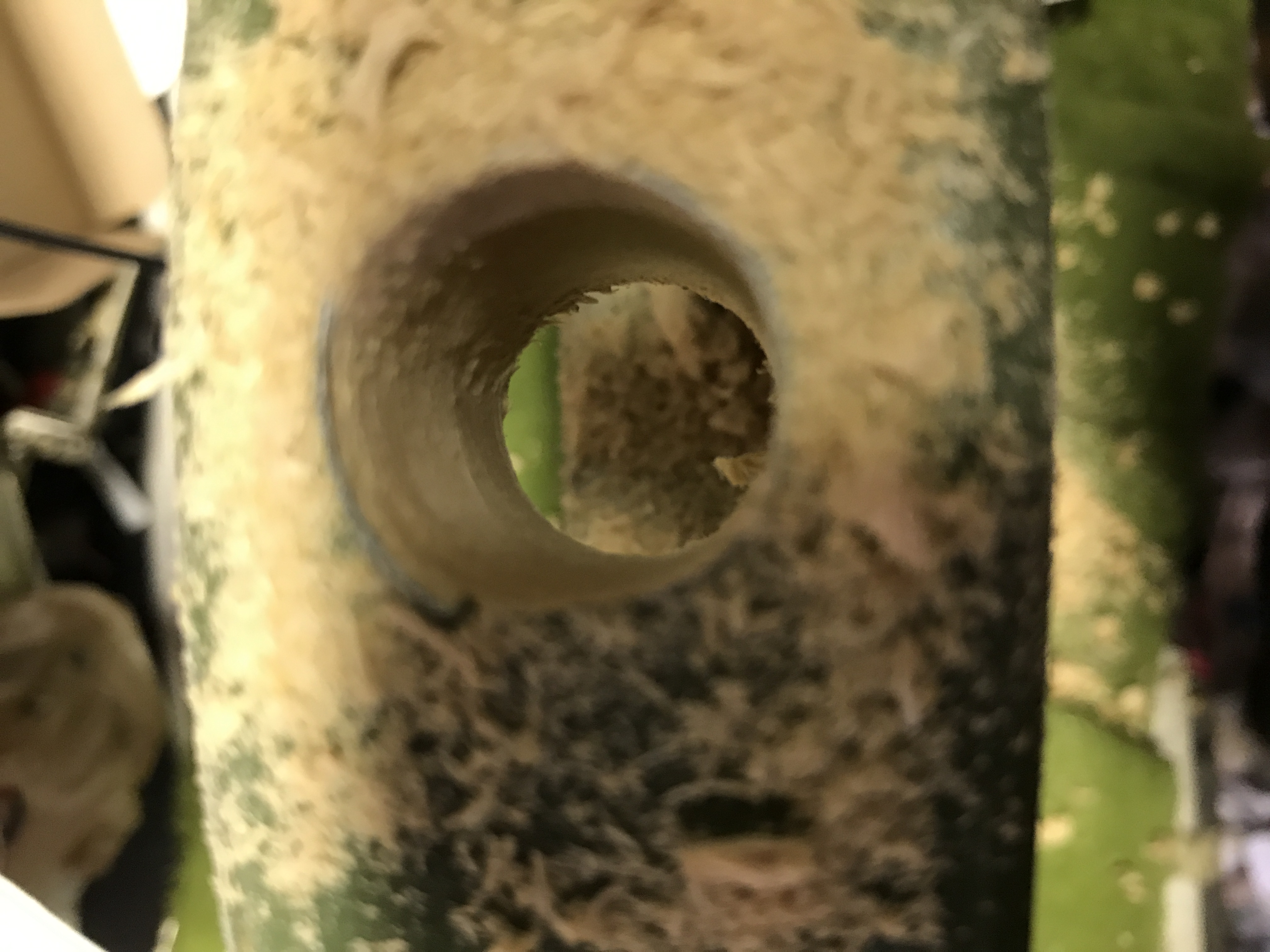
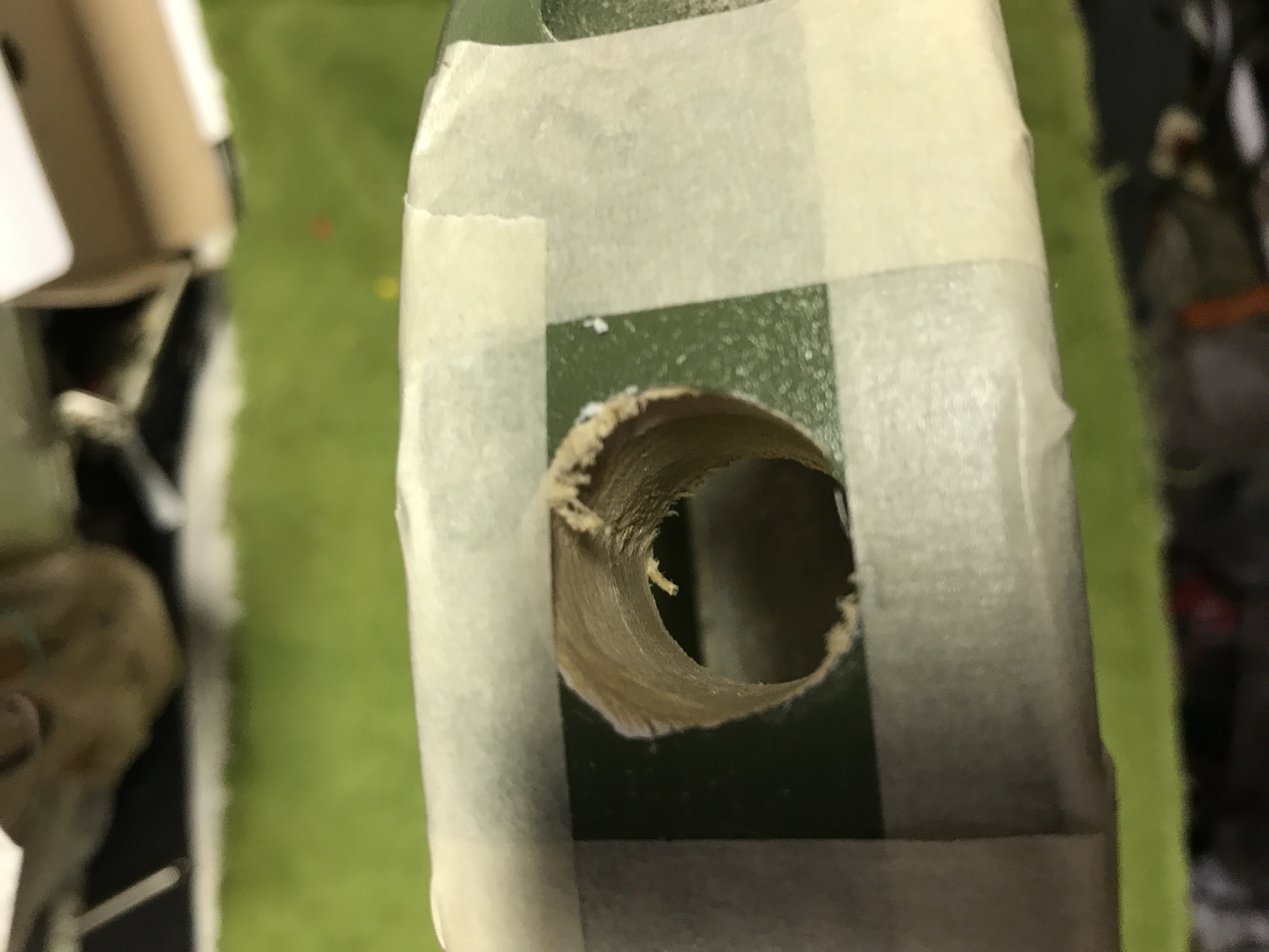
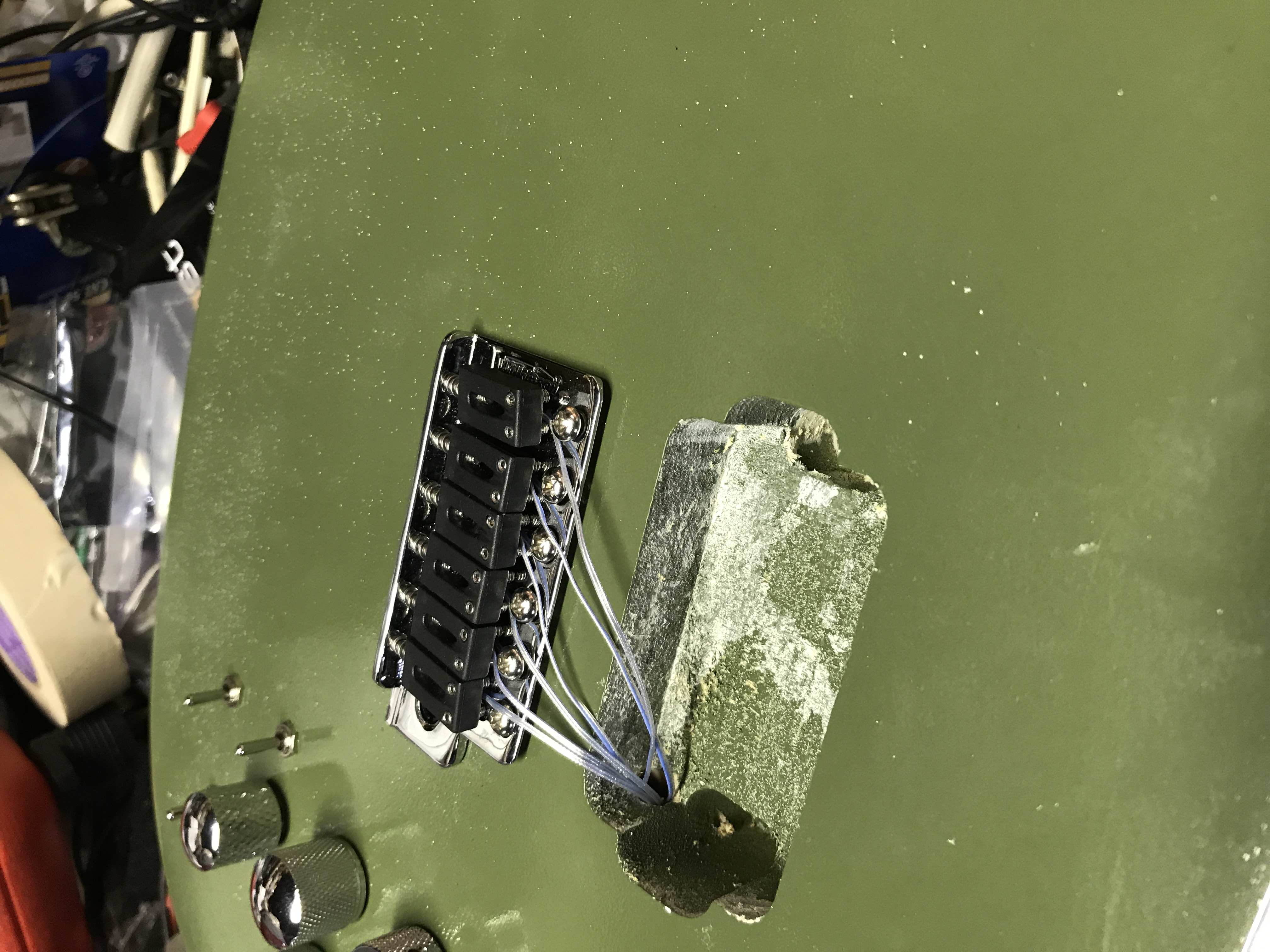
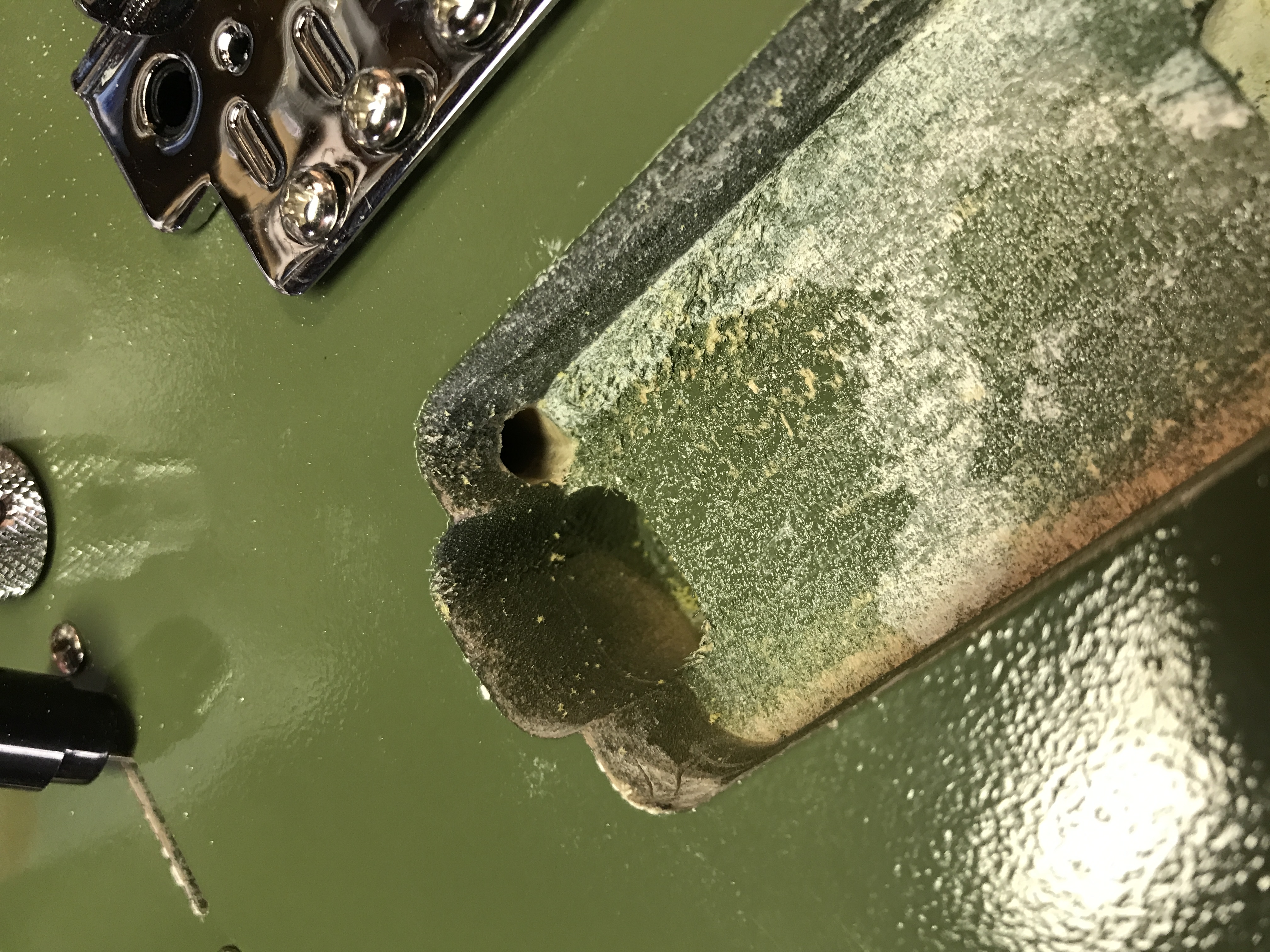
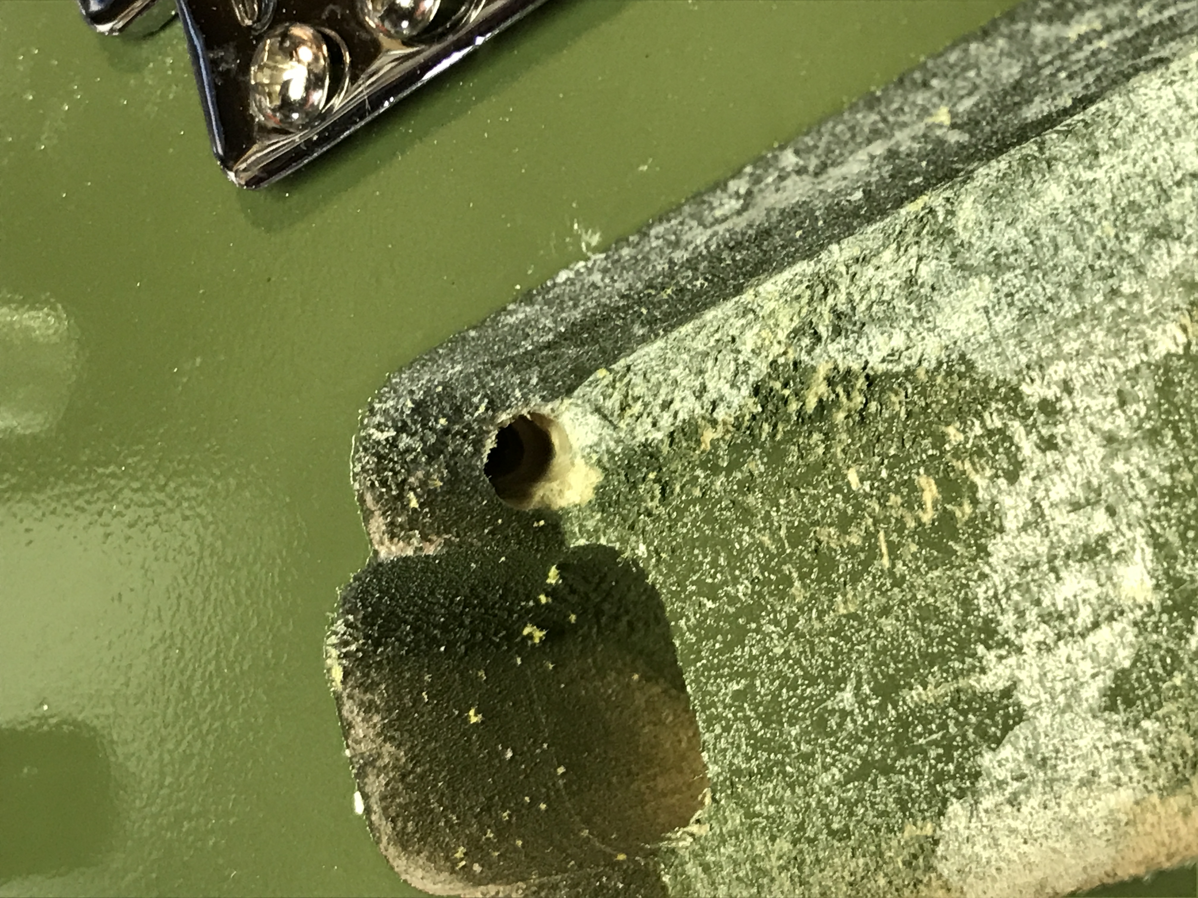
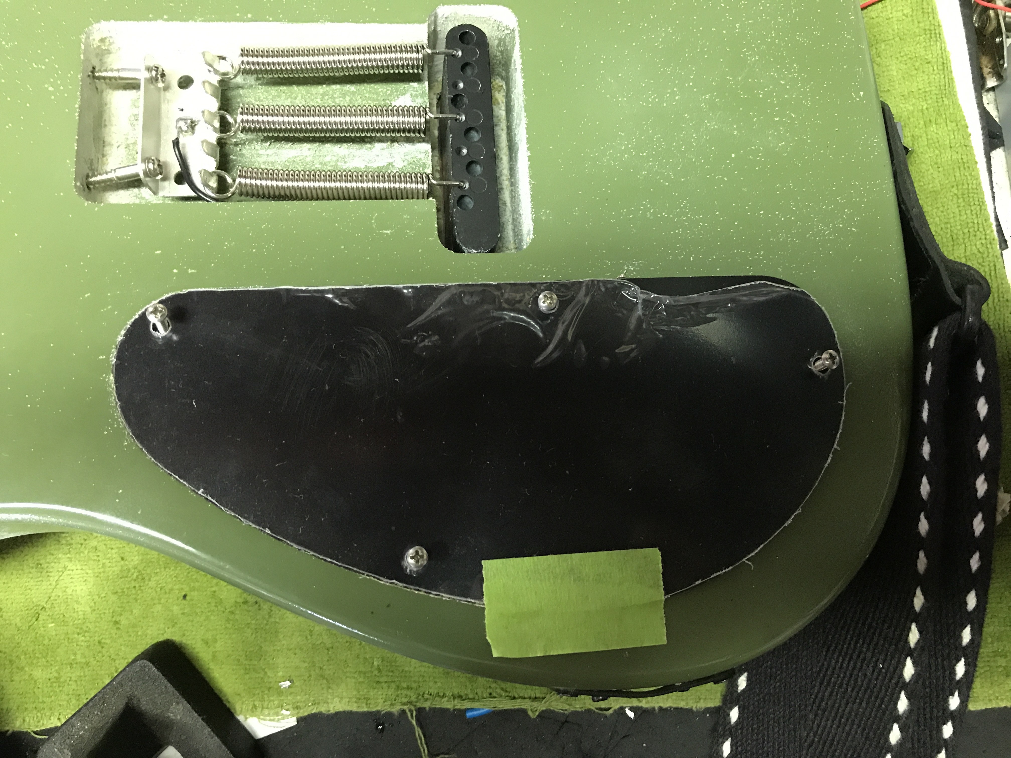
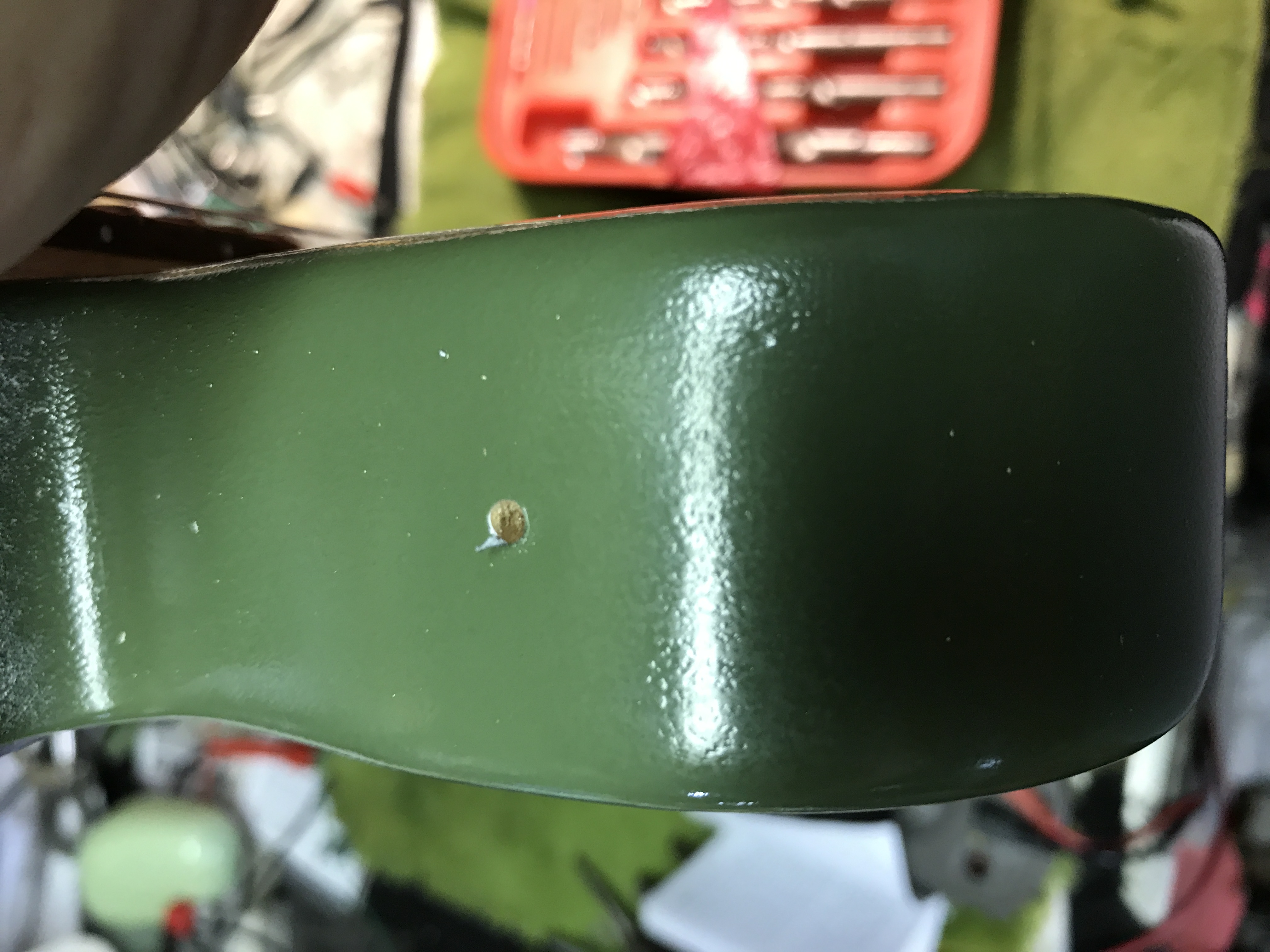
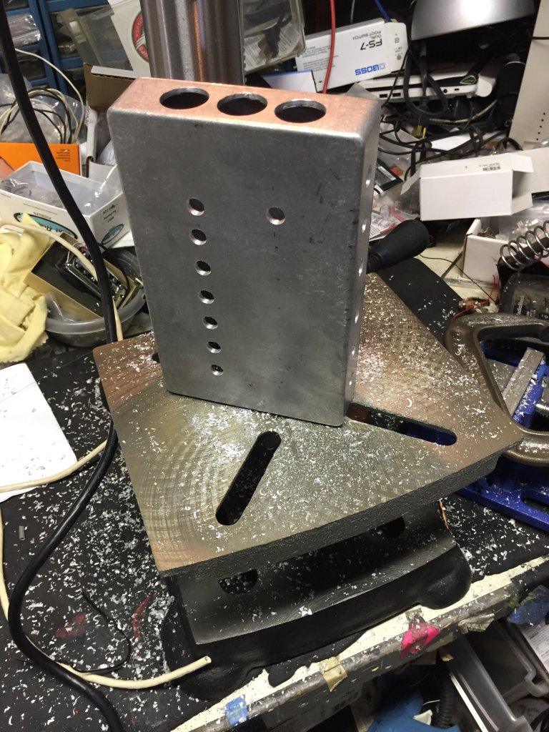
I chose not to drill the requisite holes for the additional switches, pots, and jacks required until after doing the finishing, for one reason, so as not to slow down the finishing process, and another, which now seems silly given how the finish turned out, to keep from mussing up the wood so the finish would adhere better and look good. That turned out to not matter so much. But the first hole to drill is the biggest one, which is an irregular shaped hole between the side of the guitar body and the control cavity to accommodate the Ghost jack. Graph Tech recommends drilling 3 overlapping holes in a triangular shape, which is fine if you have a drill press big enough to hold a guitar in a clamp on its side. But I don’t. So I drilled one big hole and used the Dremel with the router bit to freehand the rest of it.
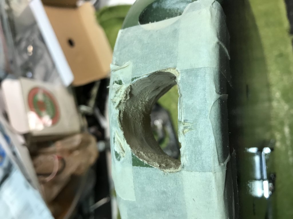
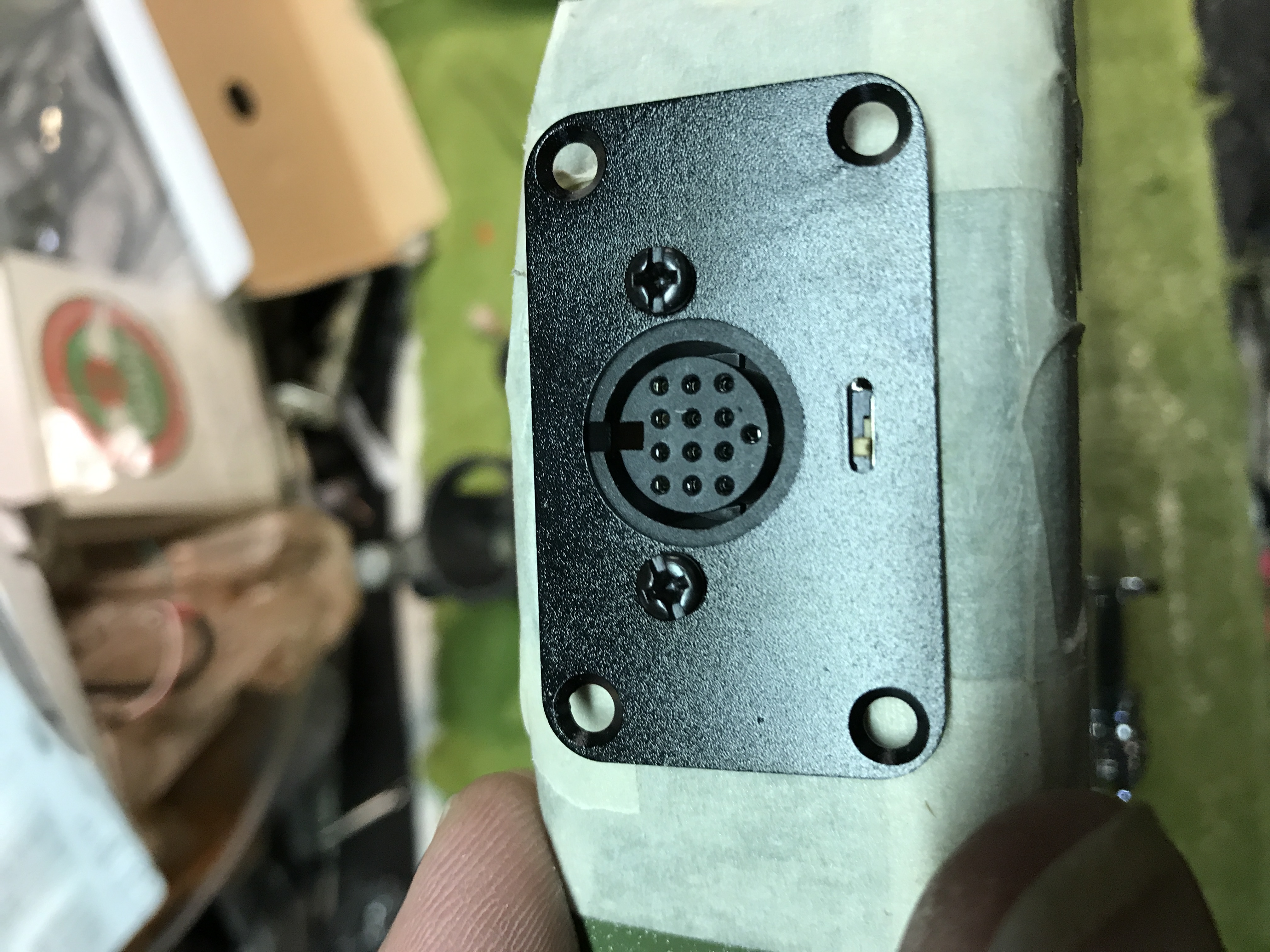
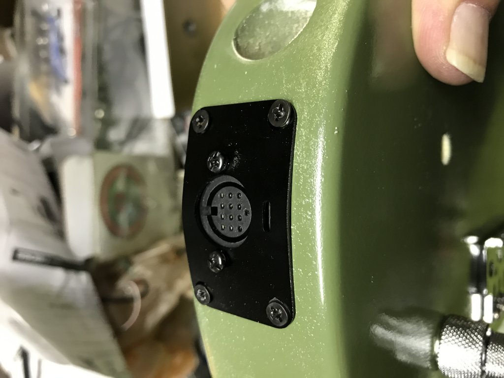
No fingers lost, so I guess it went OK. Now because the surface of the jack’s mounting bracket is flat and the Tele’s body isn’t, something has to be done to make them fit neatly and safely. So the easy way to do it is to loosen the two screws that hold the bracket to the jack, and then bend the bracket to fit the contour of the guitar body. Then drill holes for the 4 screws that hold the bracket against the body, and mount the bracket. Then tighten the two screws on the jack until they’re tight, and you’re done (it actually took way more time than I implied in this description).
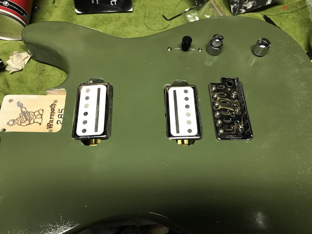
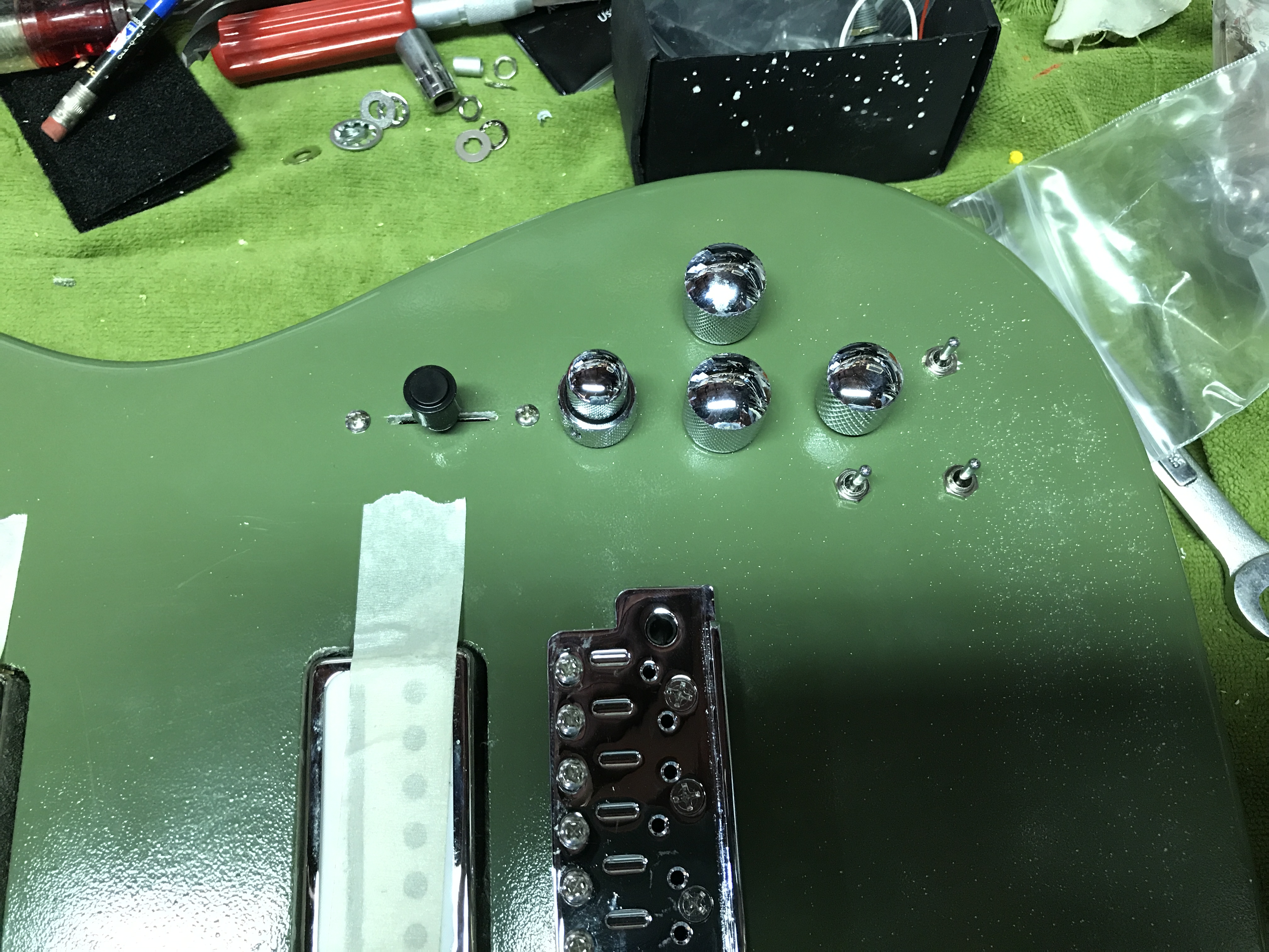
Then I mounted some controls in their assigned holes, then proceeded to locate and drill holes for the incremental switches, jack, and pots.
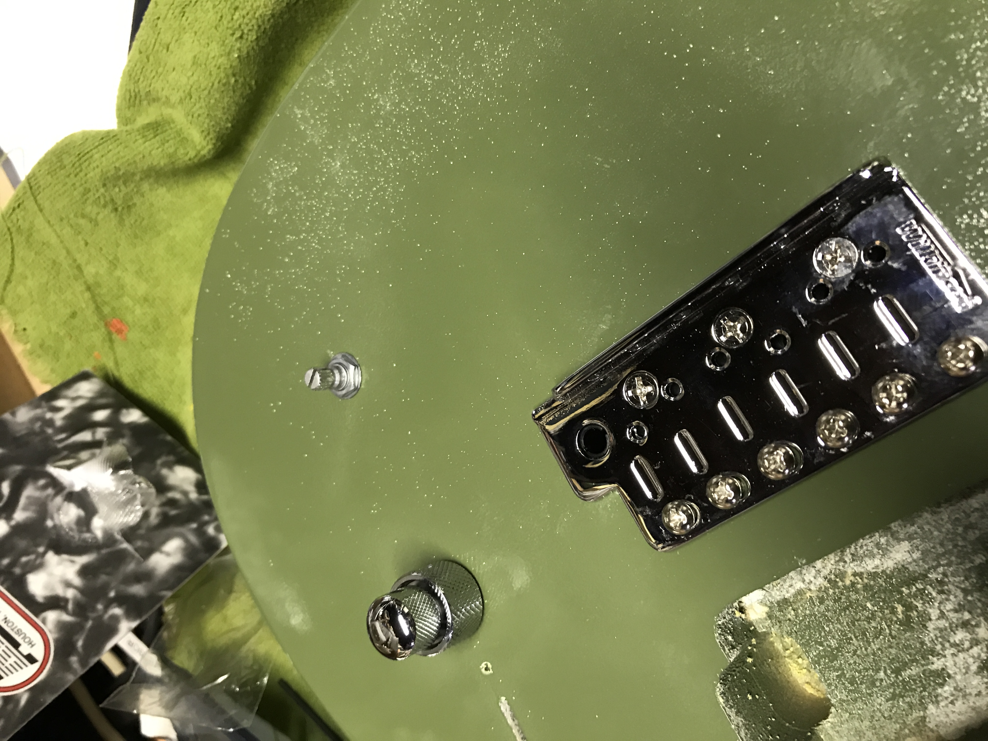

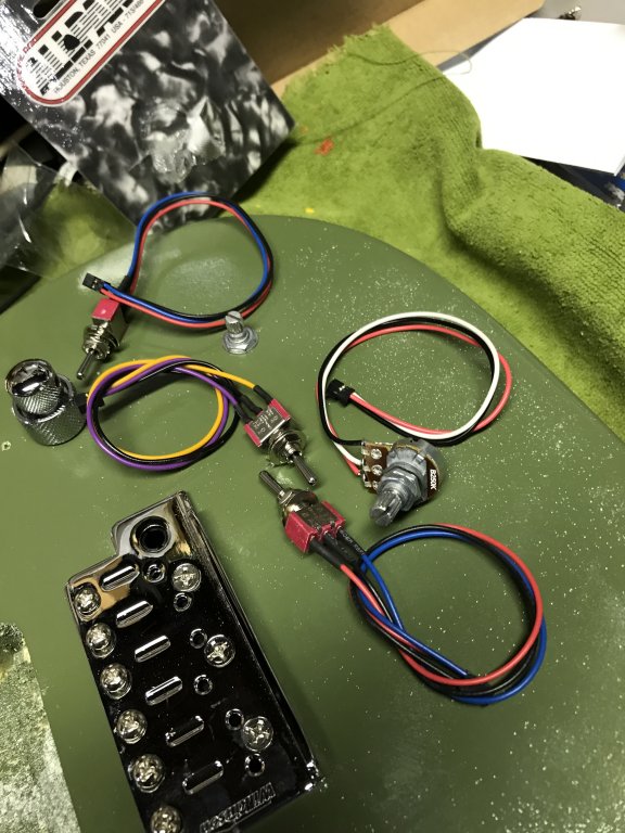

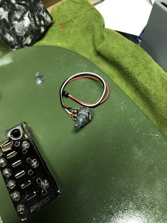
These include the synth volume, the rotary switch for the Alameda pickups, and the three toggle switches for the Ghost system. Once in, the wiring looked a little like this.
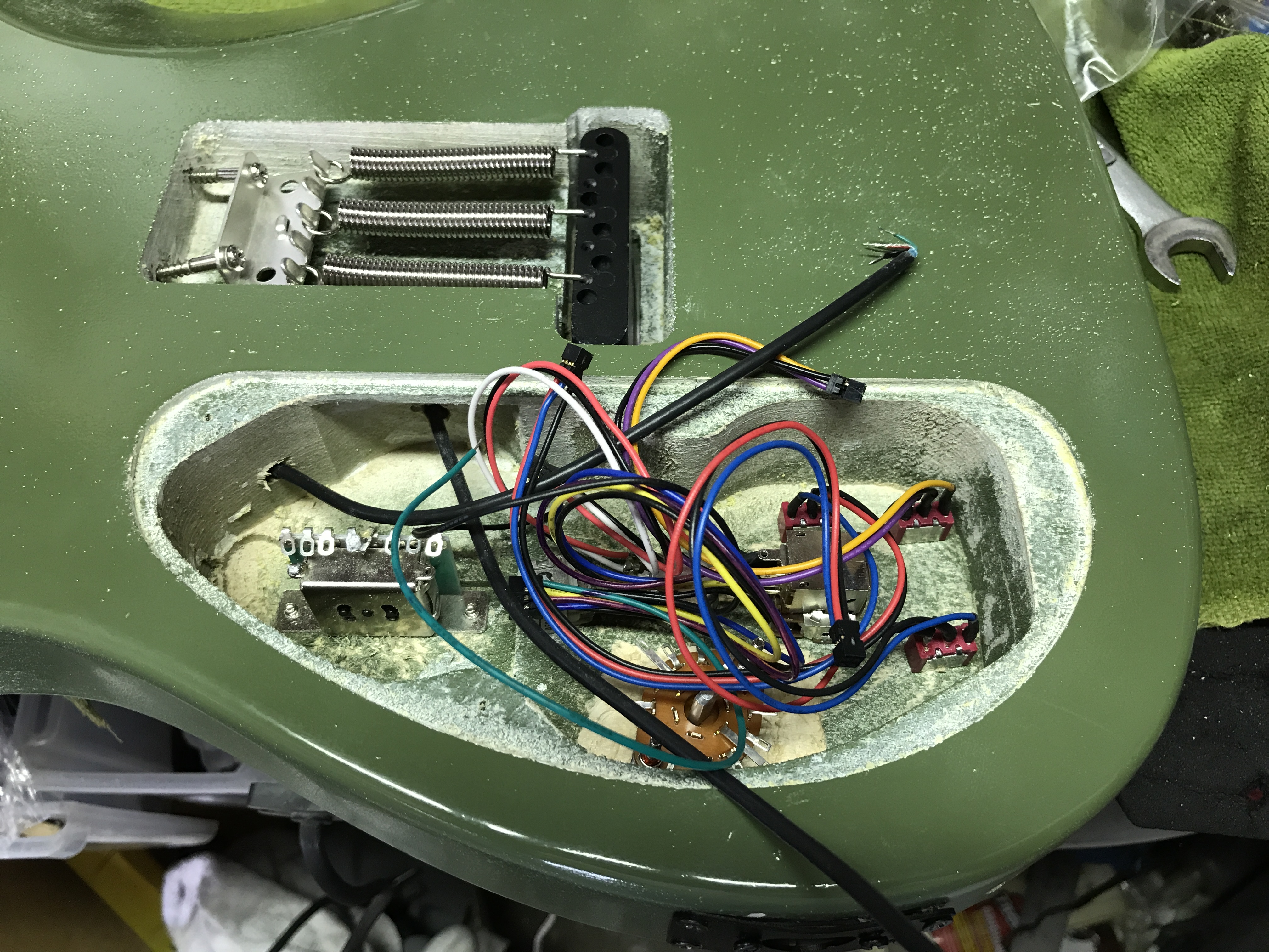
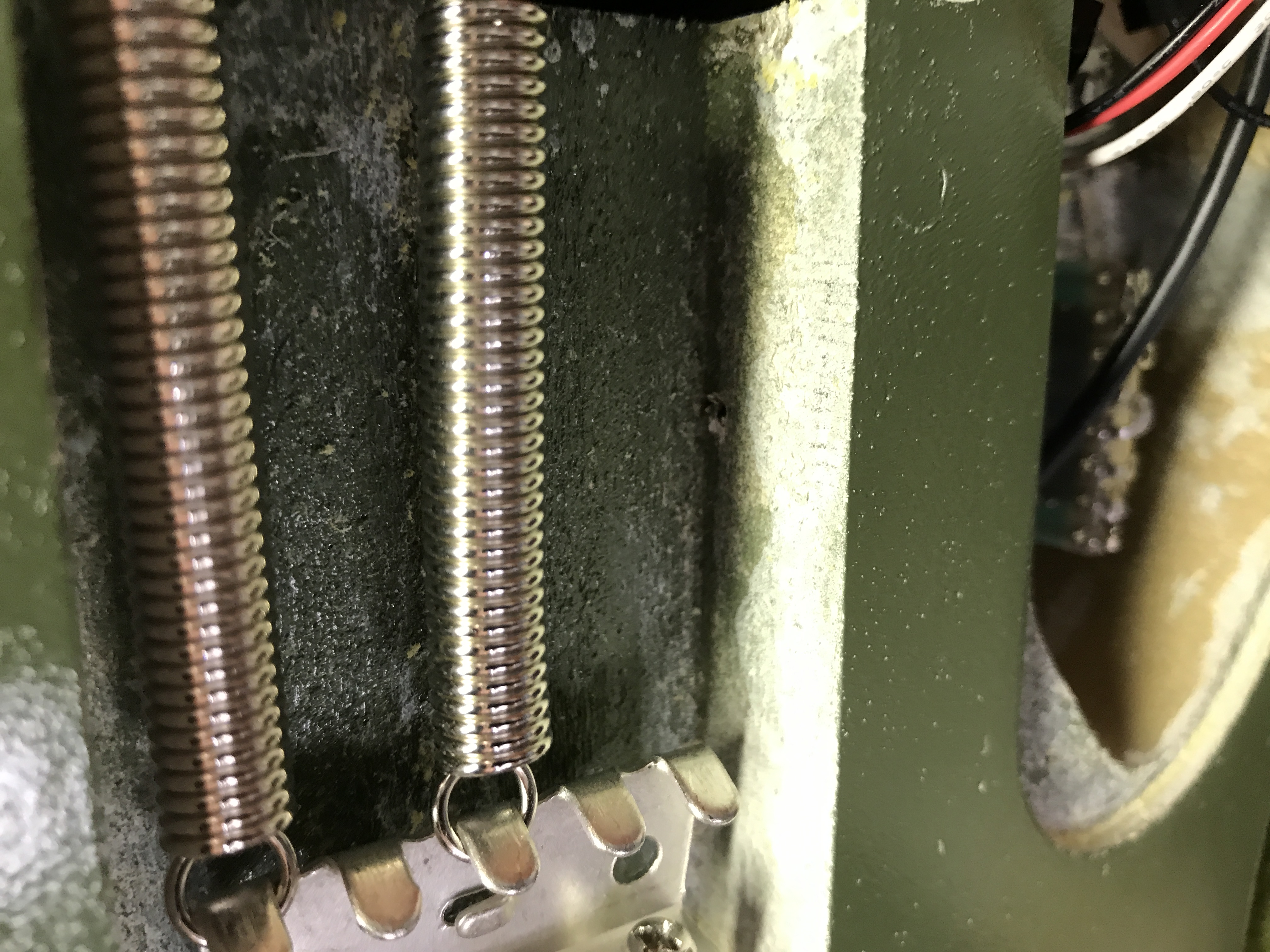
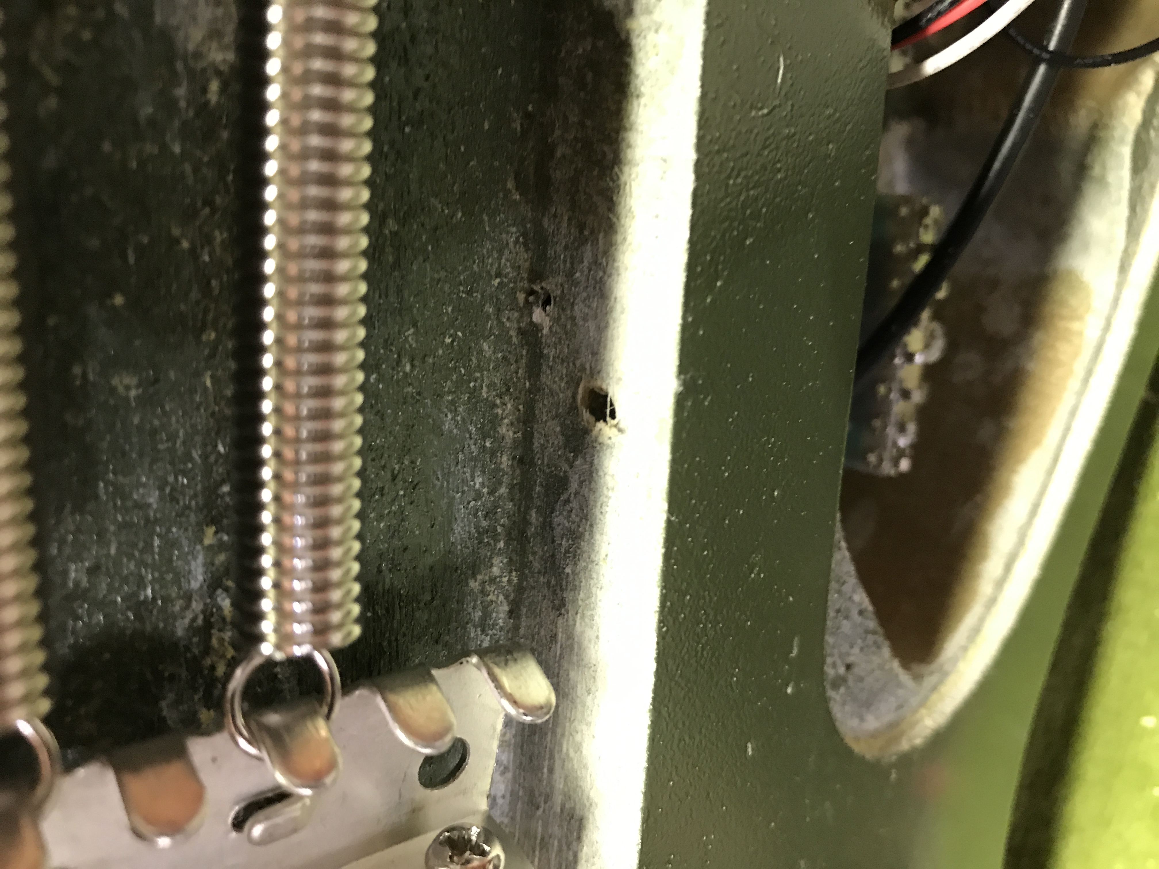
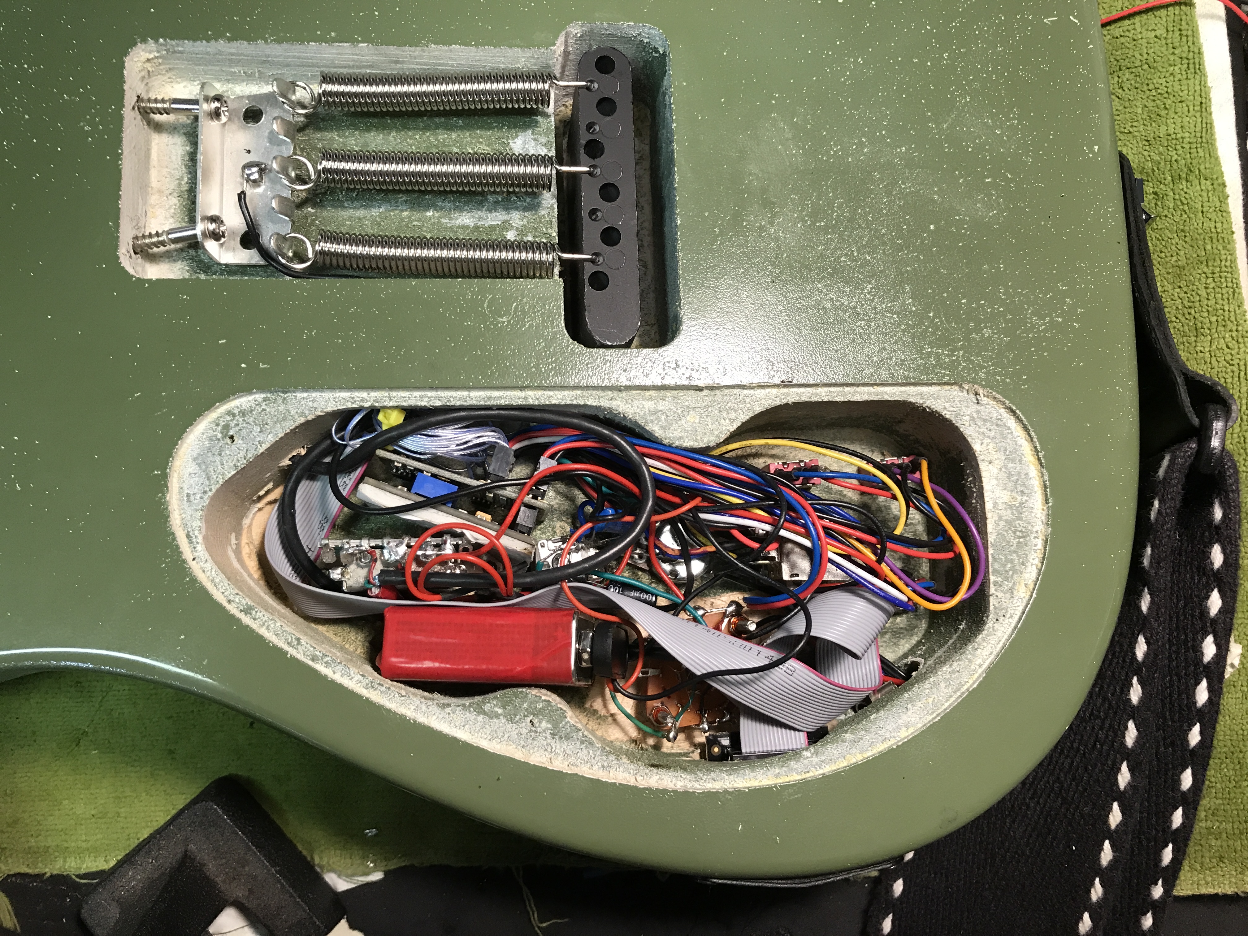
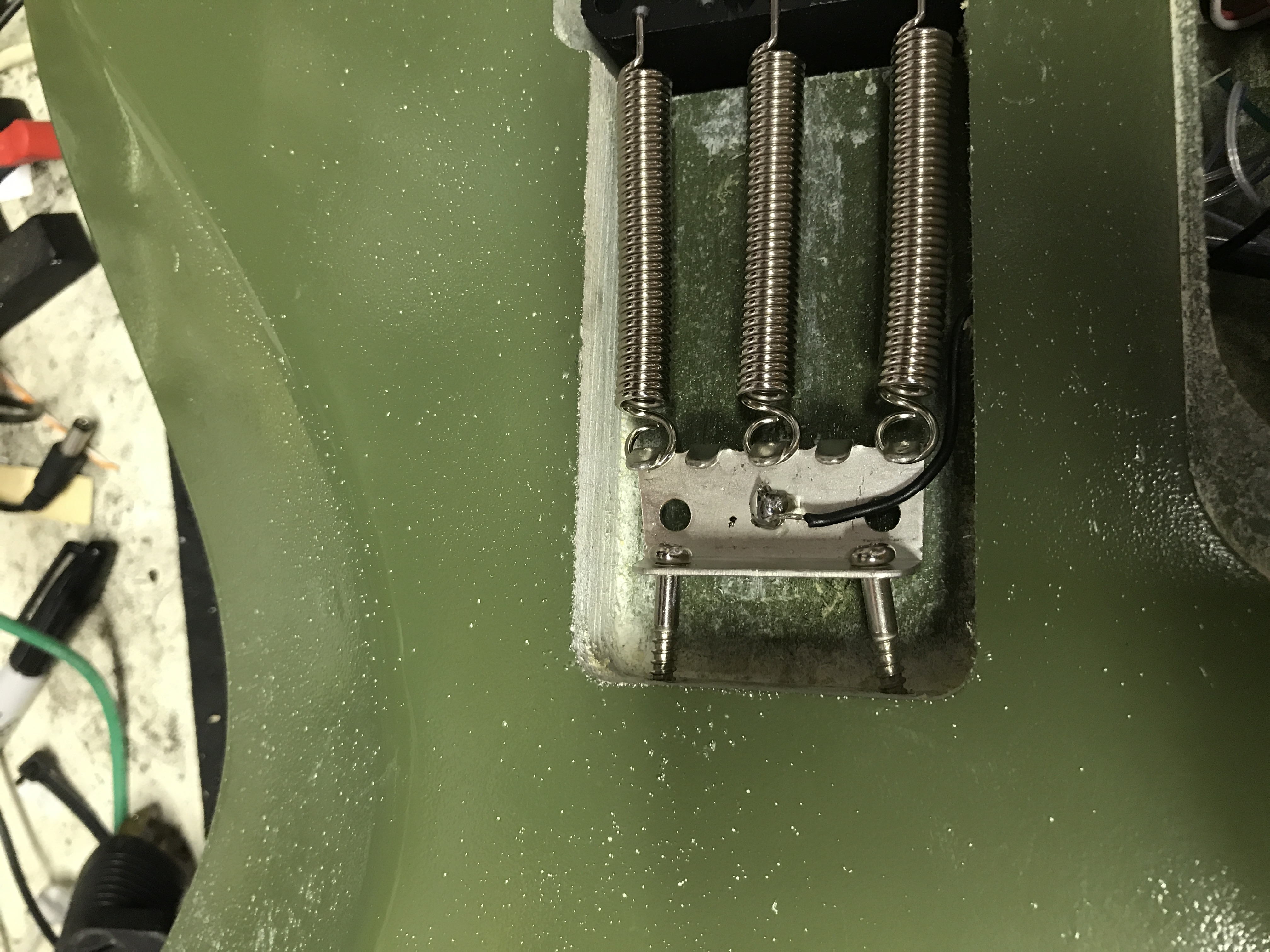
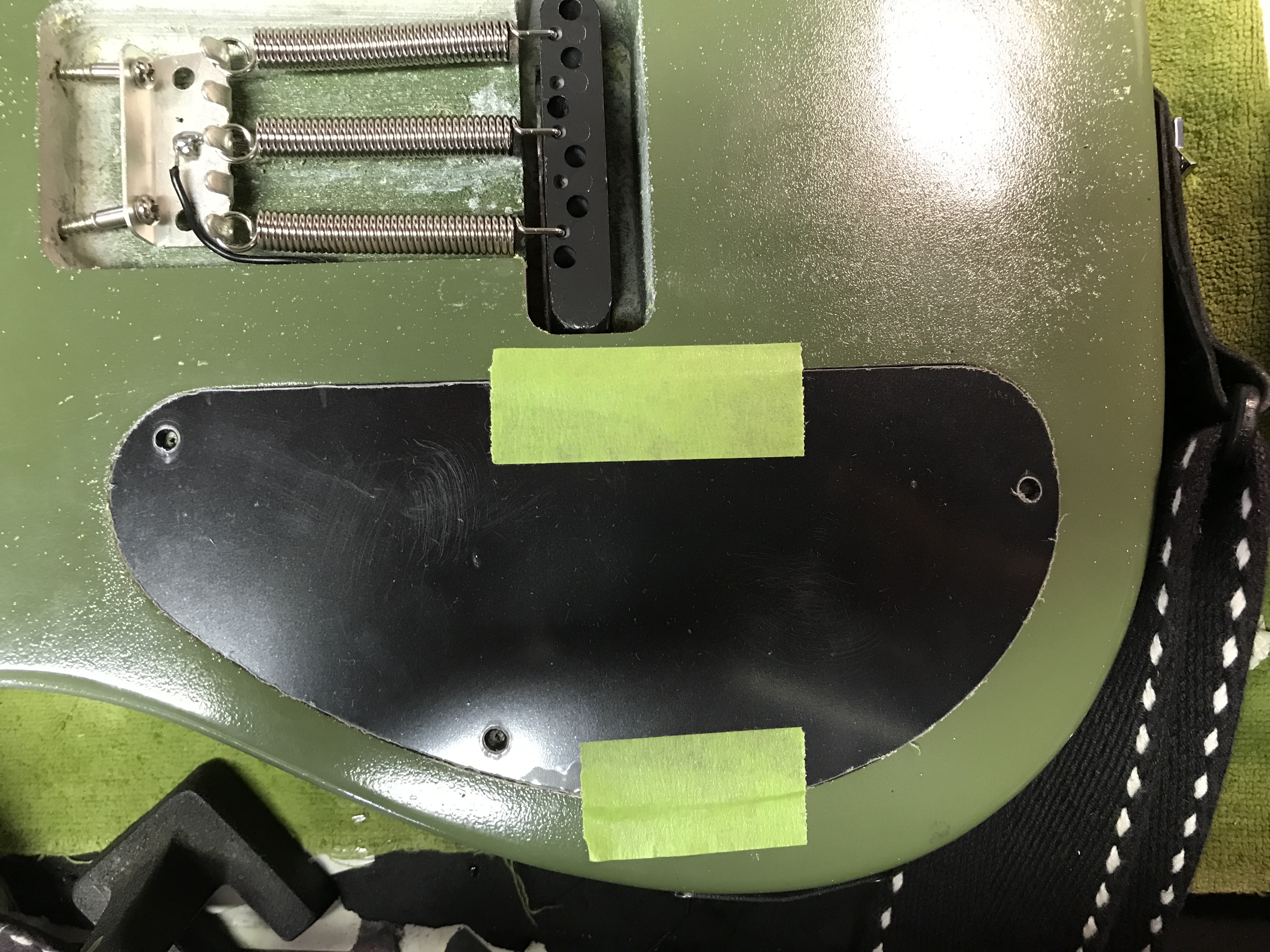
I noticed there was no easy way to get a ground wire from the trem spring claw to the control cavity, so I had to drill one.
The correct saddles and the chrome pickup rings arrived the same day, and I actually had time to work on them that day. So I started by mounting all the piezo saddles in the bridge,
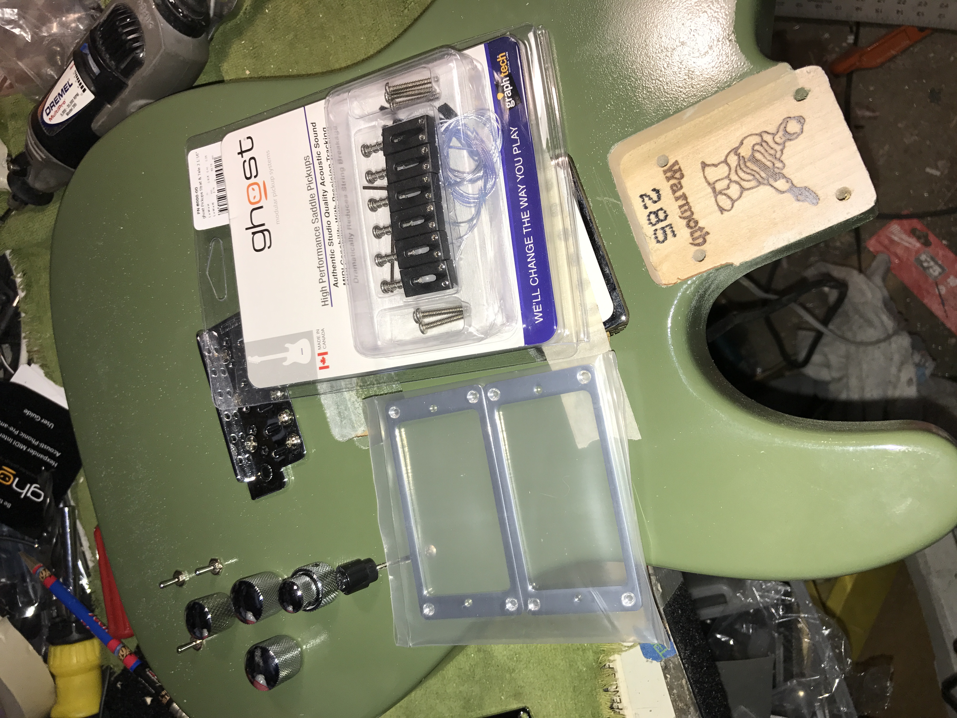

and shoved the wires down the hole Warmoth drilled for the pickup lead. This, however precluded the bridge pickup’s lead from fitting in there, so to paraphrase Roy Scheider in “Jaws,” “We’re gonna need a bigger hole.” More Dremelization, and of course, if we’re going to use those chrome rails, we’ll need to cut a notch in the corner of the bridge pickup cavity so the skinny little piezo wires can pass through the newly-enlarged hole without getting pinched. More Dremel work. Then, of course, there was some bare wood showing. This would look better if it was the same color as the guitar body, so I took a couple of Q-Tips and sprayed them with leftover color coat paint, and daubed it into the notch. Eventually, the color took.


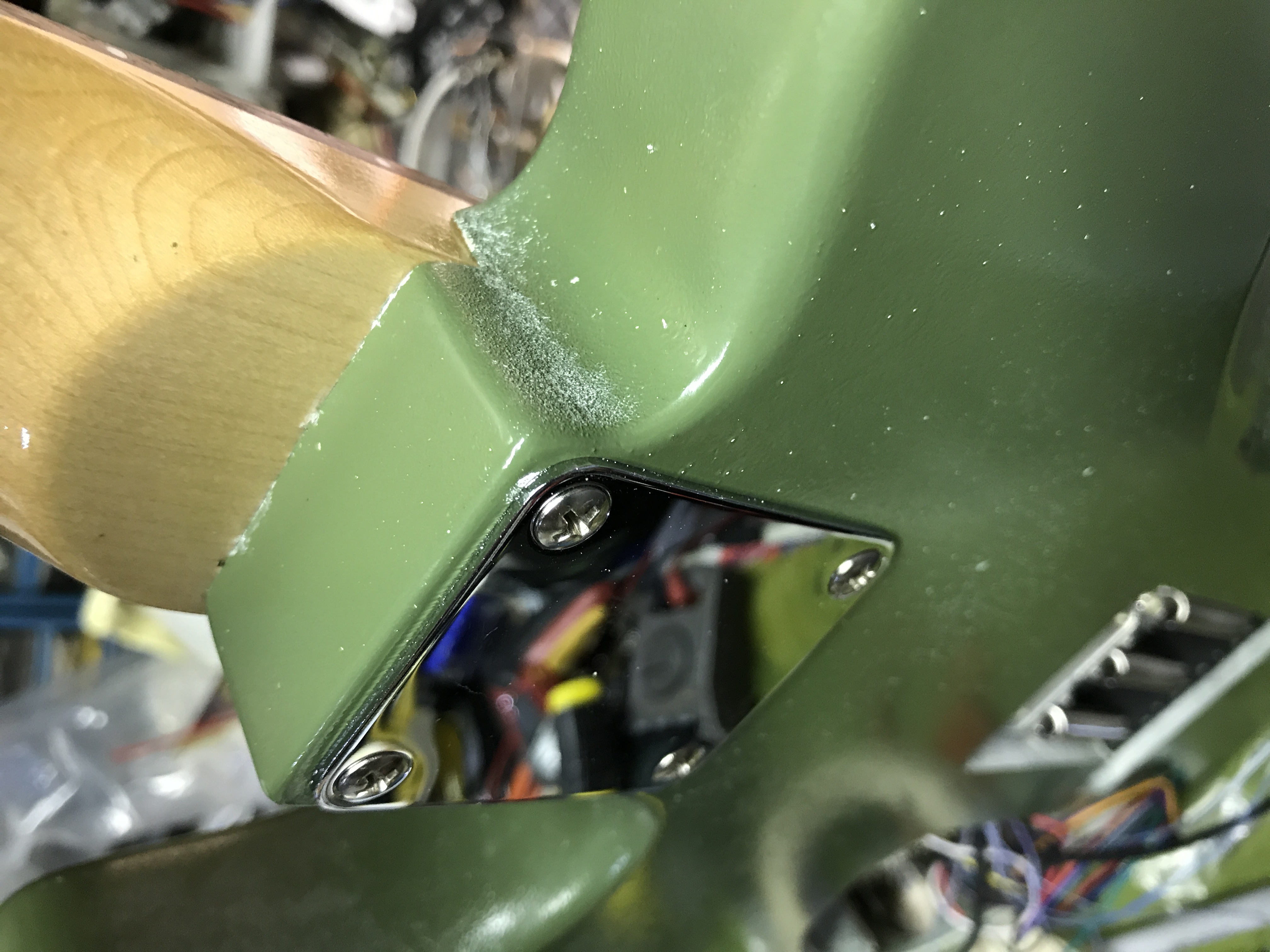
Time to mount the Alameda pickups and their humbucker rings. For best results, these should be located under the strings, aligned evenly. Well to do that, you have to know where the strings will go. And to know that, you probably ought to just attach the neck and put the two E strings on it (the other 4 will follow along). To attach the neck, you’re gonna need 4 neck screws and a neck plate. Fortunately, I had all the neck screws and a neck plate. Unfortunately, I wasn’t quite sure WHERE the neck screws were. So I went to TrueTone and got some new ones. After I got home with those, I found the original neck screws (of course). But I used the new ones, since I’d gone to the effort of procuring them.
But after you’ve attached the neck and aligned the pickups, you’ll likely have to take the strings off to do the rest of the work on the guitar, and it doesn’t make sense to use brand-new strings and then throw them away or fatigue their metal by putting them on, taking them off, and putting them back on. So I use cheap-ass strings for pickup alignment. And I have a bunch of those.
It has to have been at least 15 years ago, maybe more, that Mars Music existed. And when they had a grand opening in the South Bay, they were giving away boxes of their private label cheap-ass strings. So I befriended Chuck, one of their salesguys (only Guitar Center has salesdudes) and he hooked me up with a bunch of them. I’m down to my last two complete sets now, so I guess I won’t be building too many more guitars. Actually, that would be true even if I didn’t have a couple sets left.
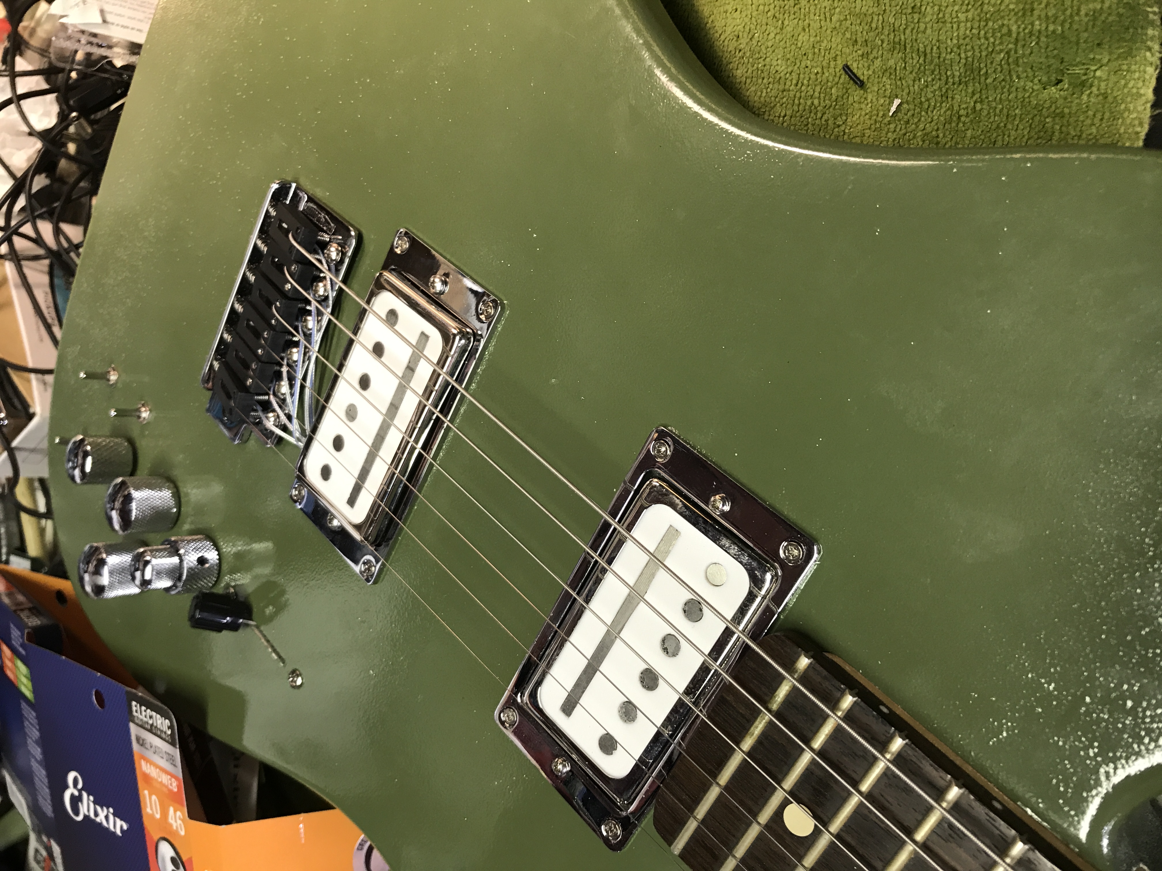
So, two E strings on, and I lined up the Alameda pickups squarely under them, then taped them down so I could drill the pilot holes reliably. Then put in the mounting screws (which didn’t come with the rings, additional kudos are in order for TrueTone for having those).


Now that the pickups are mounted, let’s finish the wiring. Well, most of it. In order to create the switching options on the Alameda pickups that enable their 5 distinct tones (“Twangle,” “Wrangle,” “Mangle,” “Tangle,” and “Jangle”), I needed a 4P5T rotary switch. Which I didn’t have. And neither did TrueTone, nor anyone else in L.A. So I had to order one from StewMac and wait for it to get there. In the meantime, I had a dodgy 2P5T switch, so I figured I could make one of the pickups switchable and find a could sound for the other pickup so the guitar would at least work until the new switch got there.
Another challenge was shoehorning that Ghost system, the circuit board, the wiring harness(es), and the required battery (not included) into that pickup cavity that was designed to hold 2 pots and a switch. Not my first rodeo with this, so it didn’t take too awful long.

Also had to wire the special 5-lug Switchcraft switching jack. The harness for this came with some pretty long leads, so I cut those down, soldered them in, and screwed them into an Electrosocket so it would fit in the jack cup hole.
Got that done and it was time to put in the ground wire for the trem spring claw. Fairly straightforward and I made the wire long enough to reach.
Now to fit the trem spring cover on and drill holes for it. Not too hard (relative to the rest of this project.

Put the cover on the control cavity and screwed it down. I’ll take the protective plastic off when I get the permanent rotary switch in.
Check the wiring. It works! Check the piezo pickups. They work! Check the synth pickups, eh, maybe later, lets set it up for playability.
OK, then. Let’s see if this guitar can actually play. First put some good strings on it (Elixir .010-.046s).
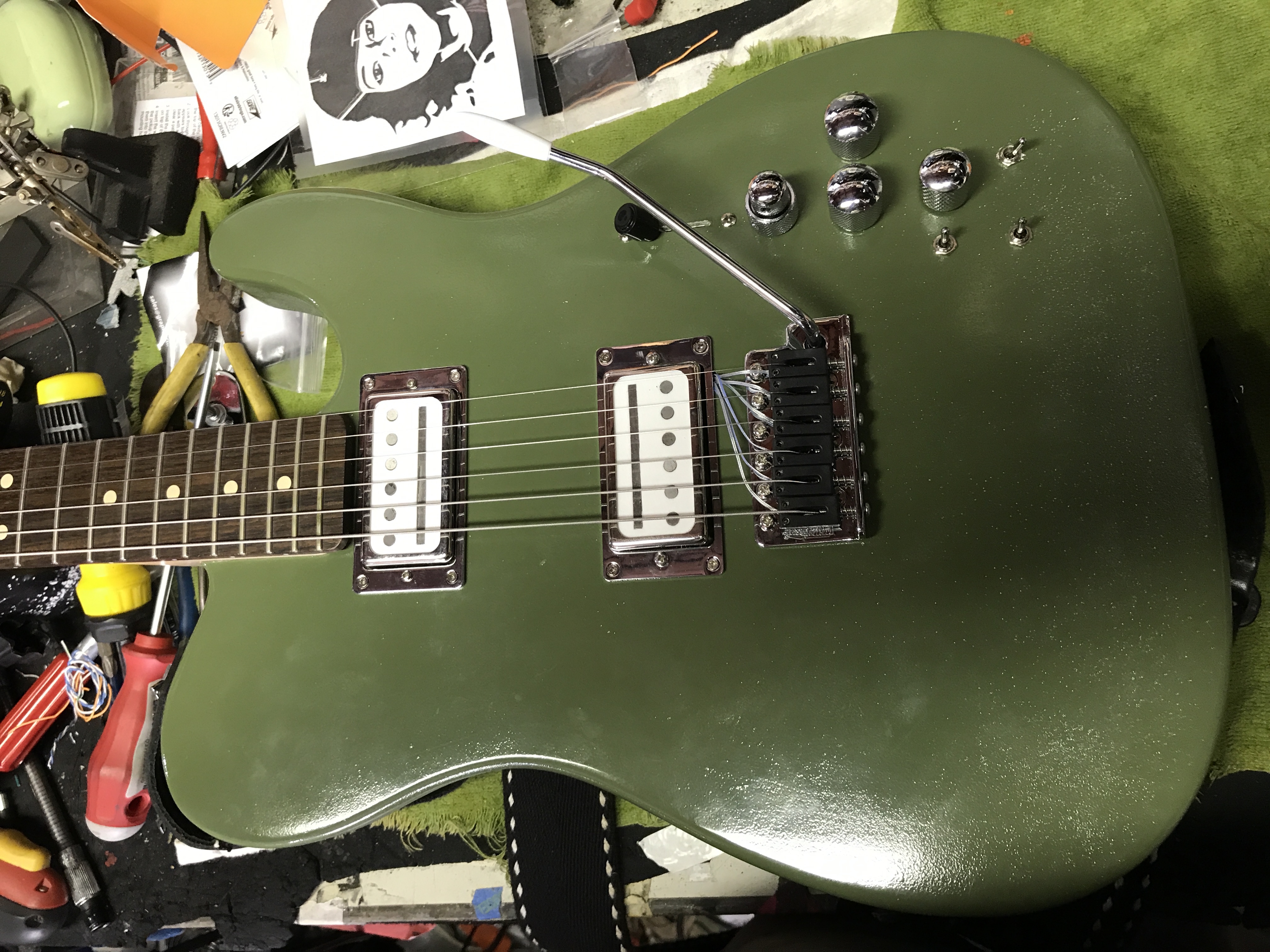

And of course, mount the whammy bar. Now back to setup. The strings were laying down on the frets, so they needed to come up a bit. Starting with the two E strings, then use a fretboard radius gauge and raise the other 4 to match the fretboard’s 12” radius. Note, I didn't do the setup upside down, though I did take the picture that way. Truss rod adjustments. Action adjustments. Then intonation adjustments. Playable? Yes!!! Goof around with it, a lot. OK, it’s safe to put the strap buttons on. I like Dunlop Straploks, but some years ago at a NAMM Show, I stopped by the Grover booth and they were introducing their own straplocks. And they came in cool shapes, like these star ones. I asked the salesman where I could get a set and he said “Here, take these!” And I’ve had them ever since.


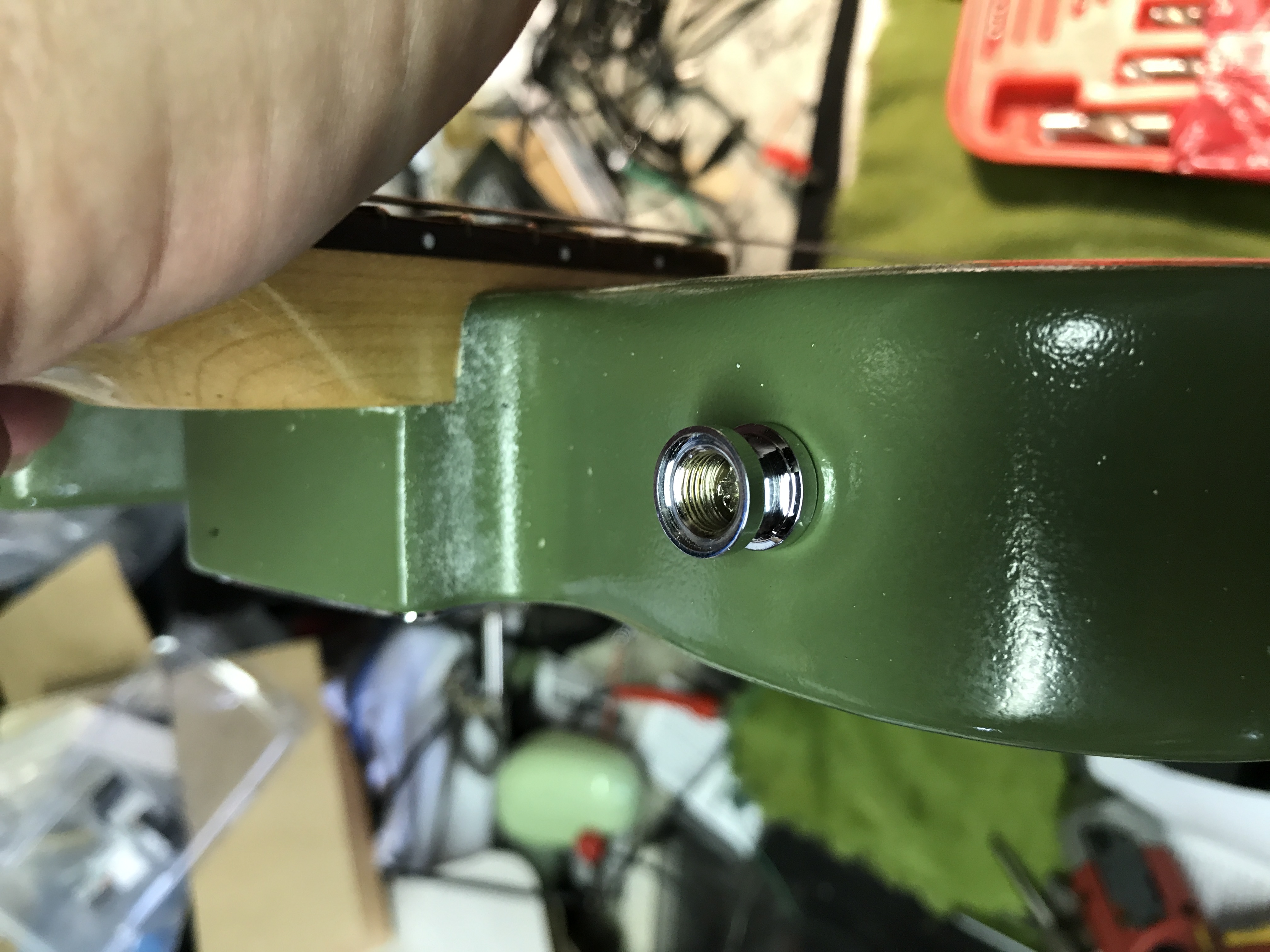
They screw into the body like any other straplock, then you put the strap on it (no attachment necessary on the strap, then you screw down the topper, and a rubber gasket keeps it from vibrating off. Pretty slick, and you can still get them in skulls, iron crosses, eagles, or stars, in chrome or gold. Them skulls look mighty appealing, now which guitar….
This neck hasn’t been attached to a guitar or had strings on it for a couple of years, so after being like Lord Krang on the Ninja Turtles and taking some time to get used to its new body, it needed a couple more setup tweaks. But now, it’s ready for fun.
The correct switch came a couple days later and went in fairly uneventfully, and now I can say it’s officially done. Oh, and the synth pickup works great, too, despite my best efforts. When I was soldering in the temporary rotary switch, I taped the ribbon cable for the synth pickup's jack safely out of harm’s way. But while I was working, the tape came loose and the ribbon cable went “Thwack!” against the barrel of the soldering iron. I pulled it off, but not before it melted the insulation. The wires are so small I couldn’t tell whether they were damaged or not, but they work, so I’m leaving them be. Ordered a replacement cable from Graph Tech just to be on the safe side.
This weekend I concluded it needs a pickguard, so I ordered a non-slotted Cabronita pickguard which I will endeavor to make fit once it arrives. Then I'll really be done. Until I think of something else I want to change.
April 7, 2017 -- The PedalBox. Or Rackabilly. Or Whatever You Want To Call It

Yeah, most people use pedalboards, but I just had to be different. I was under pressure to reduce my on-stage footprint. First they thought I should use fewer pedals, but that, of course, is crazy talk. So what’s a player to do? Relocate, was my thought. Need the pedals, no question about that, but do they really need to all be on the floor in front of me? It’s nice to have that as a dashboard for what’s going on while playing, but I don’t change settings on most of them over the course of a show, I don’t feel the need to re-sequence them in mid-song or mid-show, I just turn them on and off as needed. I could get a Boss ES-8 and repurpose my Roland FC-300 to control it via MIDI, but that would be about $600 just for the ES-8, and might be a little more complex than I need, not to mention costly.
So I thought I had once seen someone who put all their pedals in a multi-drawer toolbox, though I don’t recall how they controlled them, nor could I find any pictures online from which to draw inspiration. So the thinking process commenced. Am I doing something innovative and unprecedented, or is this just a bad idea and that’s why nobody’s done it before? I opted to find out. Along the way, I learned of another pedalboard option and was offered a beta test of it, but then that didn’t work out, so I took it for a sign that this was the way to go.
Obviously (well, it should be obvious), you can’t buy one of those passive loopers and run a pair of 14-foot cables for each pedal to and from it. That wouldn’t sound too good (or at all) and would create a cabling mess. But what if, there was a looper that could be controlled remotely, maybe wirelessly, that could turn pedals on and off using small footswitches like Boss FS-7s? And what if it sat in an easily transportable container could store the pedals safely when not in use and where their settings wouldn’t be subject to bumping or other maladjustment while in use, but could still be easily accessed? And that container could be easily loaded in and out, connected and disconnected? And what if it could control an amplifier, too, and replace the amp’s footswitch? Yeah, that’d be perfect. Except it didn’t exist. Yet.
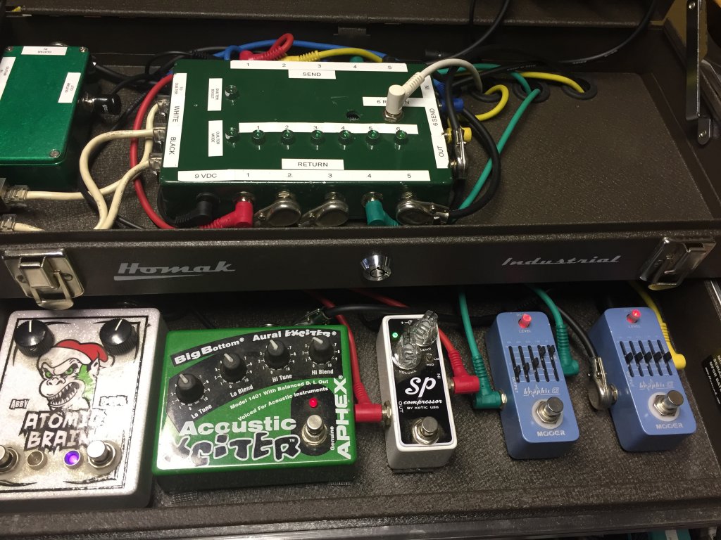
OK, I haven’t figured out the wireless capability yet (though IK Multimedia has come out with a programmable wireless MIDI foot controller, but that’s not quite what I had in mind), but I think I got the rest of it handled. And I call it the PedalBox. It starts with a Homak 3-drawer toolbox (shown above). I chose this particular model because the drawers are deep enough to hold most pedals, and it’s pretty good quality so it ought to stand up to road use, and it locks with a real “Ace” type lock so the pedals won’t disappear too easily. A modestly unpleasant surprise occurred when Amazon delivered the toolbox. That sucker is heavier than I thought it would be, and that’s without anything in it. I rationalized this to believe that will make it harder to steal.

The Strymon pedals have to sit in the top or bottom compartment because they’re the tallest I have. Probably the bottom compartment because I’ll need space in the top compartment for the control box, the wireless receiver, and the tuner. The control box, which I had to build, sits in the top so the LEDs that indicate what loop is on and what loop isn’t can be seen (for maximum coolness).
The Line 6 Wireless base is mounted upside down in the lid so when the lid flips up, it’s able to optimally receive the transmissions from the transmitter. The tuner will sit next to the Line 6 so it can be easily seen, and because it plugs right into the Line 6 anyway.
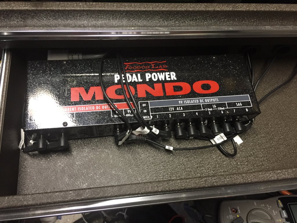
The Voodoo Labs Mondo power supply (yes, that’s really its name) is in one drawer,
and the rest of the pedals are in other drawers.
The power and audio cables go through notches or holes I had to cut in the backs of the drawers to accommodate them.

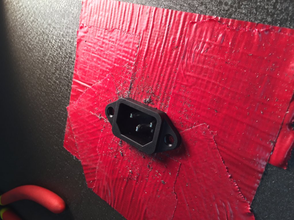
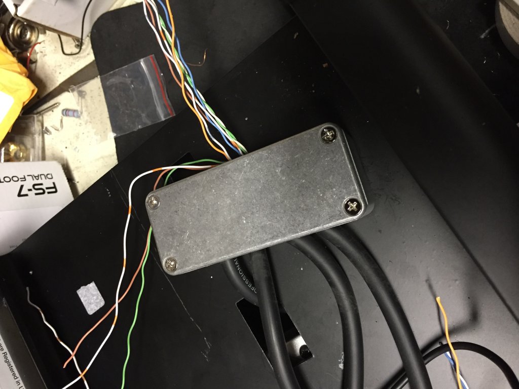
I had to cut a hole in the back of the toolbox for an IEC inlet to power the Mondo,


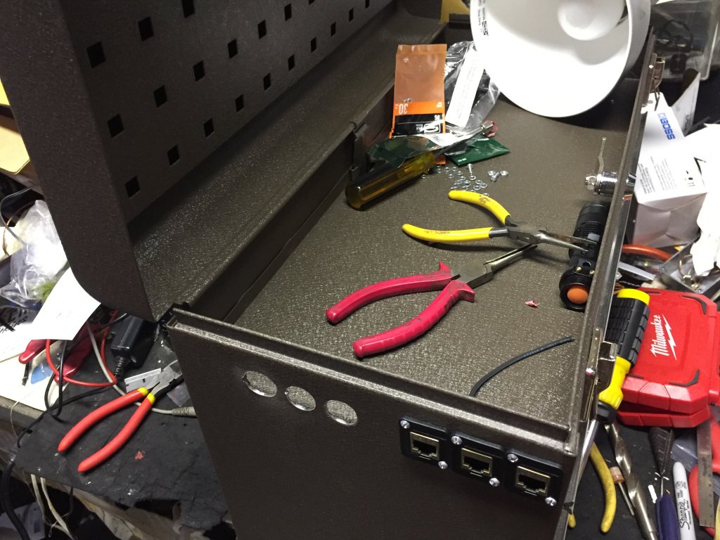
and drill some holes for a few ¼” jacks (one for an optional wired input, one for the output to the amp, one for a TRS loop to a volume pedal), and 3 CAT6 jacks.
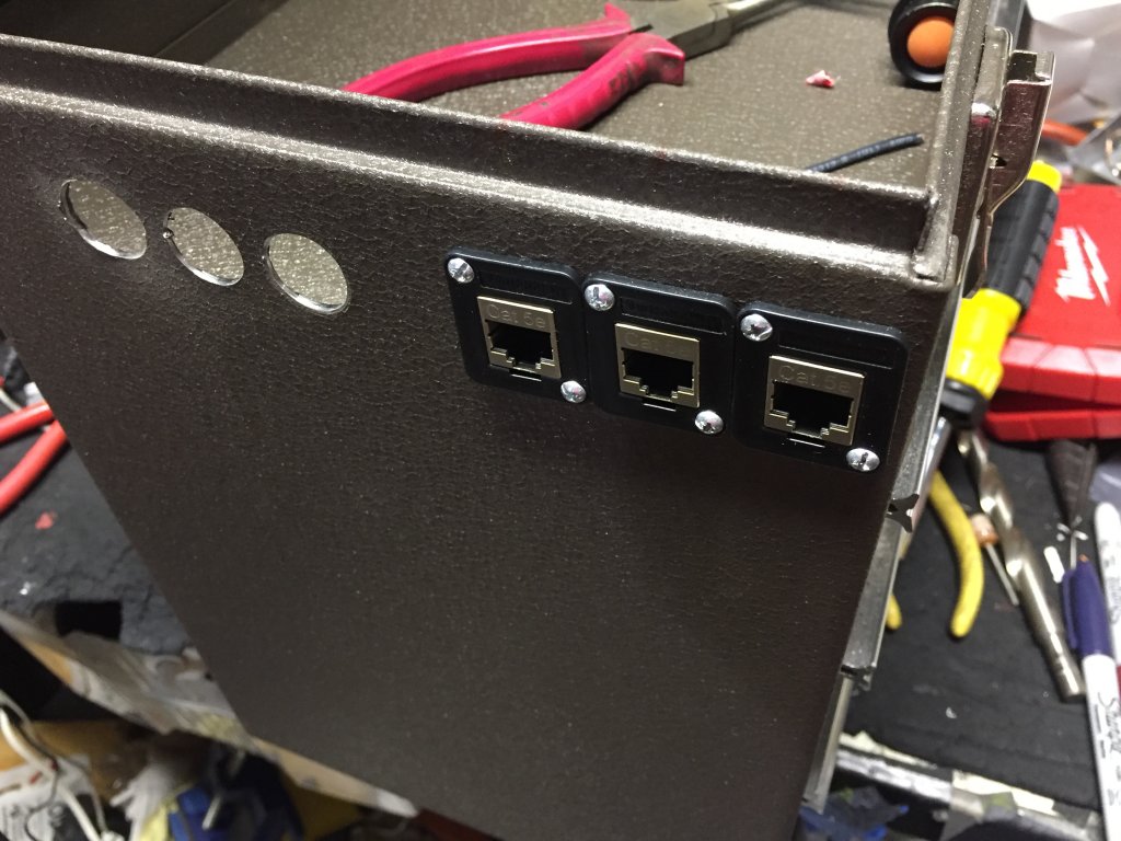
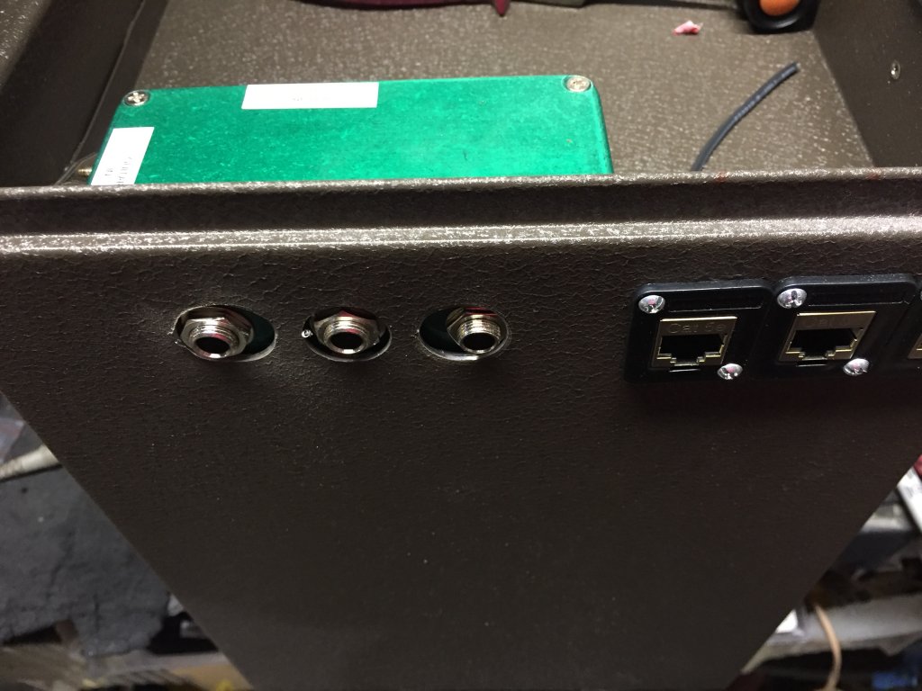

Two of the CAT6 jacks go to the footswitch board with the FS-7s on it (one provides power to the FS-7s and switches the pedals in and out, one is dedicated to the amp-footswitch eliminator, and has 5 extra conductors for future inspirations), the third CAT6 goes to the amp to drive its footswitchable functionality.
So how does it work, you ask? The secret, if there is one, is audio relays. By energizing the electromagnetic coil of the relay, a switch can do any of a couple of things: it can go from off to on, on to off, or from on to on on another circuit, or off to off on another circuit. For a loop switcher, the signal for the send and the return need to be sent to different places, depending upon whether it’s on or off (in our out of the loop). And when the pedal is not in use, its return has to be disconnected from the signal chain so it doesn’t adversely affect the tone. So by using a DPDT relay, two things are switched when the coil is energized (a.k.a., turned on), and they’re switched back when the coil is turned off.
And that’s how the Pedalbox works. The FS-7 footswitches take a +9V DC current and send it to the coil of their assigned relay. When the current hits the relay, it energizes the coil, turns on the LED (again, maximizing coolness, and nothing does that like LEDs), and the energized coil pulls the switch in, thereby re-routing the audio signal out to the effect that’s plugged into it. The other pole on the relay re-routes the returning signal to the output of the loop into the signal chain, and the signal goes on. If it’s one of the first loops, then it goes to the next loop. If it’s the end of the line (loop 6), then the signal goes to the output of the box, which goes to the amp input (well, after going through the shorting TRS jack which may or may have a Boss FV30 plugged into it). So once the input goes through, or skips, all 6 loops, it goes to the output. Shown here is a copy of my first draft of the schematic for the control box I its early stages.
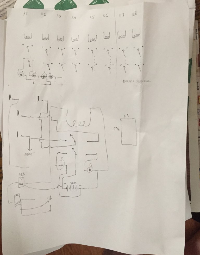
(it got a lot more complex after this)
But wait, there’s more! Besides switching effects in and out of the signal path, one of the Pedalbox’s FS-7s has the ability to turn up to two (for now; I could add more if I really want to) footswitchable options on and off on Quilter amps. I use it to switch the Mode command to switch channels, and to turn the Boost on and off. I have a few spare lines in the second CAT6 cable to do more, if I ever feel like it.
Where to start? I had a number of points of uncertainty in this project, not the least of which was whether the audio relays would work, and how they would sound. So I did a little research to find what make and model relays work the best for an application somewhat like this (since I couldn’t find any record of anyone’s having done it before). Panasonic made some highly-regarded audio relays, as did Omron. Then I remembered the coils had to be 9VDC since that’s what the power supply was providing (yes, I forgot for a moment that the Mondo has a couple of 12VDC ports that I wasn’t even using, so I could have done that, but, too late now). That cut down the number of options, but there was still an adequate selection. So I ordered some on ebay, and set about building a prototype circuit. I took an old Hammond box I wasn’t using, drilled a couple more holes in it to mount some more jacks a power connector, and I opted to let the LED hang out the edge.

I’ve been told in the past that if the circuit sits inside a metal box, using shielded cable inside the box isn’t necessary, but when I first breadboarded it up with long individual strands of CAT5 copper, it hummed like a mofo, and that just wasn’t going to work. So I replaced those with pieces of the Mogami cable I usually use to make patch cables out of, no longer than they needed to be, carefully shielded and all shields grounded. Success! Crazy? Yes, but this just…might…work!!!
So then came the next part, sourcing all the hardware and components. In the course of my travels, I ran across a pedal parts supplier with the best name ever, “Bitches Love My Switches,” at www.bitcheslovemyswitches.com. There I found LEDs with the resistors already installed, Neutrik ¼” jacks, both mono and stereo, and the big Hammond-type box that everything will get shoehorned into. Amazon was instrumental in finding cool things like flat 25-ft. CAT6 cables that take up practically no space, panel-mount RJ45 pass-thru jacks for the side of the toolbox, actual punchdown RJ45 jacks for the control box, drill bits to drill the holes for those jacks, and so much more. But once sourced, to the drill press!
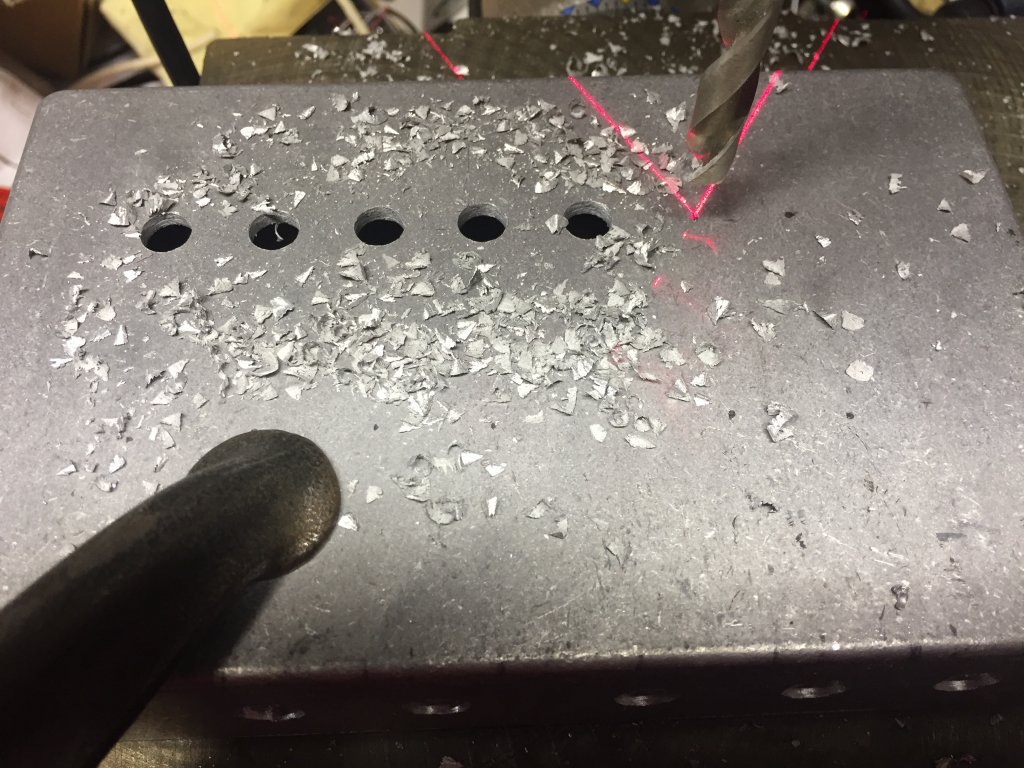
I spent the last half of the Super Bowl and the brief overtime putting 23 holes in the box, and I’m still waiting for the drill bits to arrive to make the remaining 3 holes. Once that’s done, then it’s time to (attempt) assembly. I’ve always marveled at those, which include my dad, his ham radio friends, and the occasional electronics teacher, who said things like “I could fit that into a box this big” (usually while approximating the size with two fingers on one hand). Well somehow, I need to get 8 relays, 9 LEDs, 14 ¼” jacks, 1 power jack, and 3 CAT6 jacks into this box, and a fair bit of wire, too. This is another challenge for this project. Maybe I should have etched a PC board…no! I haven’t done that since high school, and I’m not sure I want to do that again for this project.
My timing could have been a little better, but I just had to go cheap on shipping. The punchdown CAT6 jacks are going to be one of the last things to arrive, and not having them to gauge how big to make the holes for them (the drill bits arrived already) kind of puts assembly of the control box on hold. So until then, I’ll be further testing the circuit, to answer questions like “Will the FS-7s actually work with the relays?” Will there be too much voltage drop across that skinny 25-foot cable?” “Will the little cables provide enough power to run the FS-7s?” Gonna have to try it all and find out.
My worries were a bit unnecessary. The punchdown CAT6 jacks arrived the next day, and with a little drilling, they fit into the box just right.
Unfortunately, they blocked 2 of the ¼” jacks from mounting in their intended locations, so there are now two “ventilation” holes in the box and two previously unplanned jacks on the top. It was a rainy day, but I painted the box anyway once I had all the holes in it (some sprinkles gave the paint job a little more texture than I’d planned, but it did get painted),

and after doing that, realized I hadn’t drilled the countersinks in the box for the mounting screws for the CAT6 jacks. Whilst waiting for the paint to dry, I opted to test the functionality of the FS-7 switches with the relays and LEDs, over a long CAT6 cable. Happily, it all worked. Haven’t been able to test the ability of the box to power the FS-7, especially 4 of them, but until I get all 4 of them, I won’t be able to.
And so commenced the assembly. First, mount all the hardware. That took a little while, as all the jacks needed to be installed, and some rotated so as not to bump into each other and short.

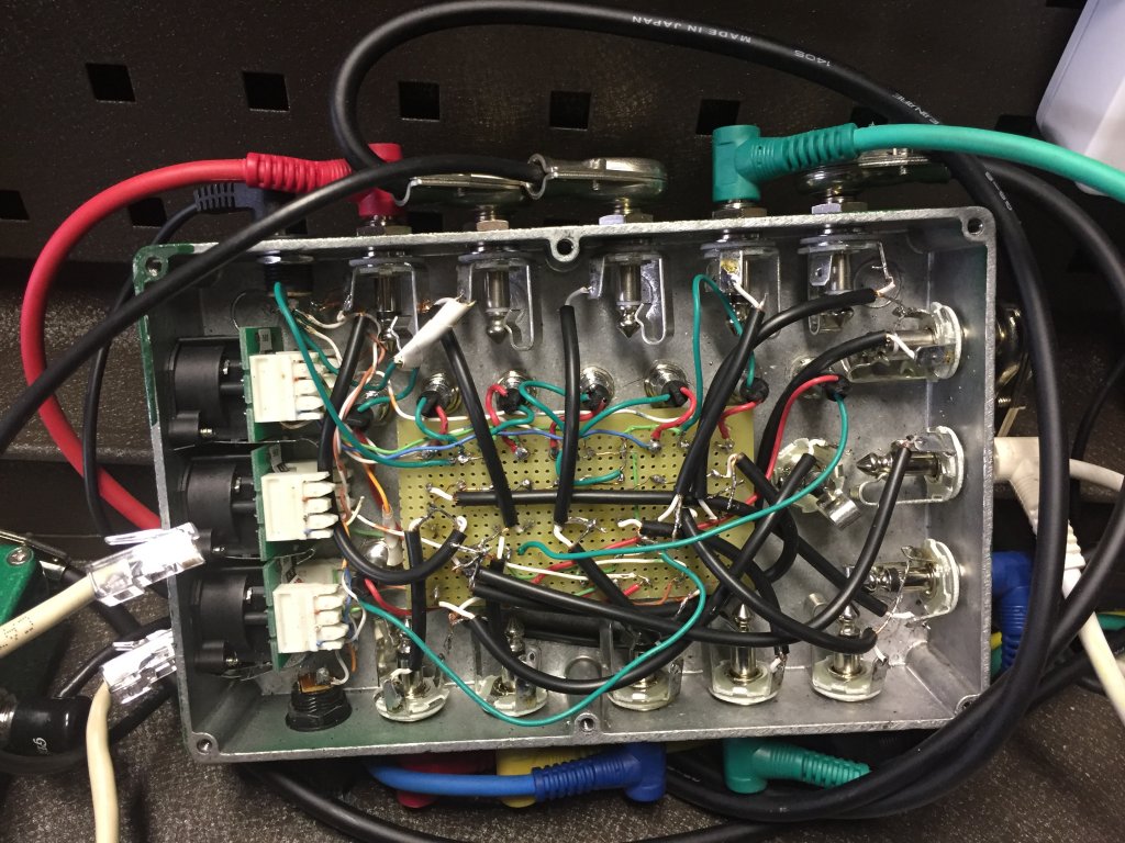
Assembly and wiring were a bit tedious, especially the wiring. I initially planned to use shielded cable to minimize the potential for added noise, but recalled that no one else uses shielded cable inside their aluminum box stomp pedals, so I opted not to. And I just stuck the relays to the top of the box with Dual Lock. This looked like hell and was a mess to wire.

Then when I got it done and plugged it in, yikes, was there ever a hum problem. OK, time to go with shielded cables. And while I’m at it, a neater way to wire it, with shorter leads. Not sure why I didn’t do this before, but how about perf board to mount the relays on, and provide a neater, simpler means of connecting? Duh. And I was going to need some thinner shielded cable. And I wanted it now. So off to Fry’s Electronics I went, where I found affordable perf board, but no bulk shielded cable small enough to meet my needs. I did, however, find inexpensive RCA patch cables with thin shielded cable, so I bought two 6-footers and cannibalized them (I ended up only needing one). With the perf board, I was able to use much shorter leads, except to and from the loop jacks, but was able to shield all of them. At first I was planning to mount the board using Dual Lock for standoffs and putting the relays right-side up for neatest appearance. Then I decided that doing so would make the wiring a nightmare, so instead I stuck the Dual Lock on a couple of the relays and mounted the perf board with the contacts facing up, thereby facilitating soldering all the leads on. When I finally got it all done, A) it worked, and B) nowhere near as much noise. Still a little, but tough to notice. In my first iteration of wiring, I figured I’d probably damaged a few of the relays by overheating with all the soldering, desoldering, and resoldering I’d done to them (yes, I know I could have avoided all this by using IC sockets, but that didn’t occur to me until I was well into the project), so I ordered some more (the good news: they’re only $1.50 apiece, the bad news, they have to come from China, which takes a while). But I got tired of waiting and re-used the original ones, and they’re fine.
And of course, the day I finished rewiring with the perf board and the old relays, the new relays arrived. Guess I’m all set for building another one of these contraptions. Which I’ll probably never do.
Now that the relay control box is complete, it’s time to prepare the rest of the project for assembly. Keep in mind that the proof-of-concept on this project is running only a couple of days ahead of actual execution, and I’m trying not to horribly disfigure anything so it can’t be returned or repurposed if we encounter unrecoverable failure along the way.
The next step is the foot controller. This consists of 4 Boss FS-7s and a Boss FV-30 mini volume pedal. They’re mounted on an On Stage pedalboard, a one-piece aluminum board that comes with a gig bag big enough to hold the board, the pedals, and the cables.
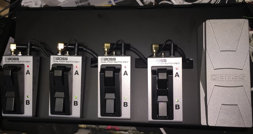
The CAT6 cables connect between the PedalBox and the foot controller via a surface-mount dual CAT5e jack (since I’m just passing DC current on the cable lines, I’m not too concerned as to which category my jacks and wiring are) underneath the board. The FS-7s use ¼” TRS cables, and while I could have used CAT5 or 6 cable into some right-angle TRS plugs, 3 strands of CAT6 cable aren’t terribly rugged, and I was concerned about breakage, so I bought some TRS audio cables and cut them to fit. But as I found out when I tried to wire them, the leads on the TRS cables are 16AWG, which is a little too big to punch into the punch-down block on the jack. And I also had to mount a 9 VDC power jack to power the LEDs in the FS-7s, so in the words of Johnny Cash in “One Piece At A Time,” I’ll need the help of an “A-dapter kit.”
In my case, the A-dapter kit is a small Hammond box with 5 holes drilled in it:
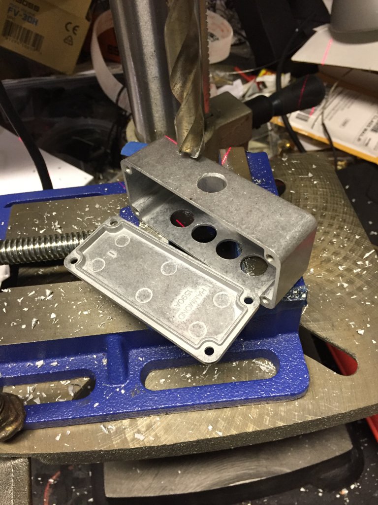
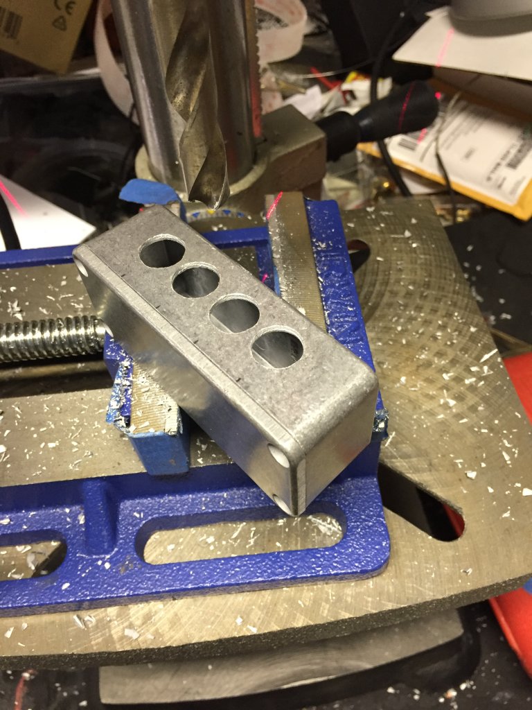
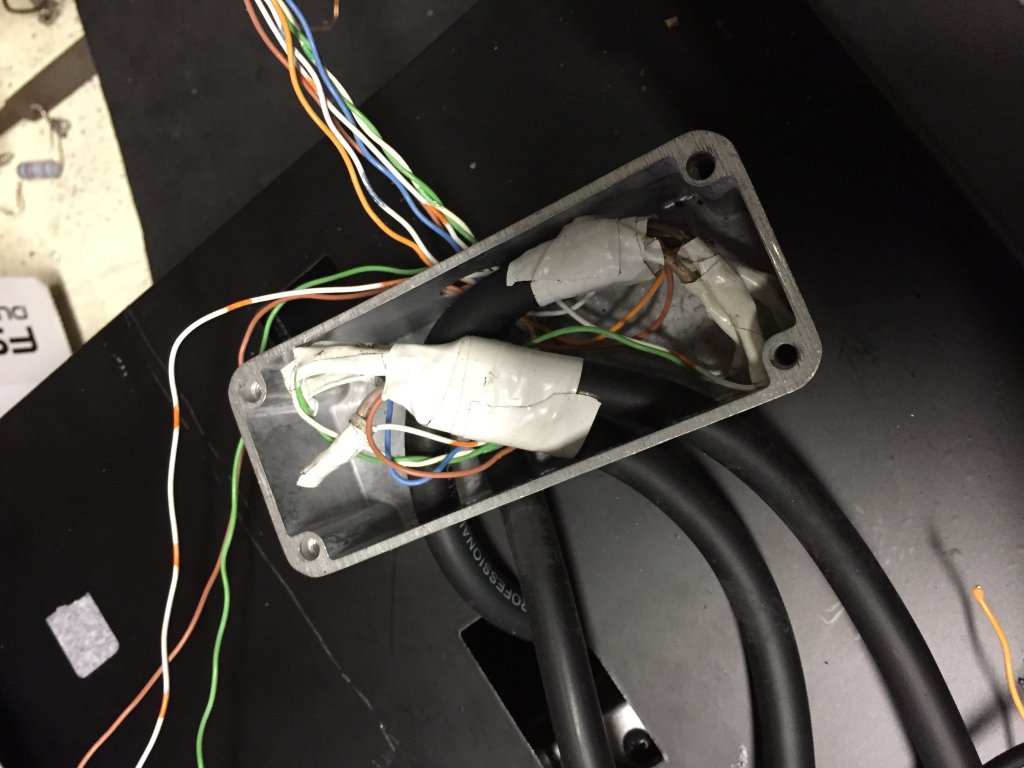
4 for the TRS cables to come in, and one for the CAT5 cables to go out. Inside the box the larger wires are soldered to smaller wires, and then the smaller wires go to the punch-downs on the CAT5e jacks. The A-dapter kit (I’ve since renamed it “The Consolidator Box” since that’s essentially what it does, i.e., consolidate 12 leads down to 9) will be mounted underneath the pedalboard, directly behind the CAT5e jacks.
It would have been nice to make them easy to disconnect, but I need to be concerned about not connecting audio ground to 9VDC ground, and the fact that I’m passing +9VDC through these footswitches, including the sleeves on all 4 TRS cables, well, I don’t want +9VDC to come into contact with audio ground, I suspect things wouldn’t go well if that happened. It wouldn’t be a problem or even a risk if it weren’t for the fact that the volume pedal is also down on that board, plugged in with cables with exposed grounds. And while it won’t likely come into contact with the footswitch cables, it could come into contact with the pedalboard frame, as could the footswitch cables. I think some shrink-wrap insulation is in order. Or at least some electrical tape.
I had some spare time where I was nowhere near the project, so I thought it would be a good idea to put in some thinkin’ time and mentally test my hypotheses as best I could, and perhaps identify and sequence the remaining tasks. I came up with 24 steps (not quite Hitchcock’s 39), and spent part of Sunday (this project has taken so long, I don’t recall WHICH Sunday I’m talking about here) evening working through them.
Upon discovering I was going to need two 9VDC power runs to power both the control box and the SwitchBoard, I needed to find a way to install a second 9V jack in the control box. The good news, there was already a hole in a convenient place where it would fit. The bad news, the diameter of this hole needed to be enlarged. But it’s an aluminum box, and my step drill bit made pretty quick work of it. A little more wiring, a little blowing out of metal fragments created by the drill, and the second jack was installed, the CAT6 jacks rewired, and everything put back together and tested to make sure it all still works. In addition, I completed the footswitch wiring on the pedalboard, which included reducing the TRS cable leads to a size that would punch down on the dual CAT5E jacks, hiding that mess inside a little Hammond box, modifying that duplex CAT5E box with a 9V power outlet jack to plug the footswitches into, and mounting the Hammond box and duplex jack on the bottom of the pedalboard. Tested all of that too (successfully).
Now (then) came the part I’d been putting off until I was sure it was going to work: drilling holes in the toolbox. I haven’t counted exactly how many holes I’m going to have to drill in this poor box, but when I’m done, it’s not going to be much good as an actual toolbox. So far, I’ve put 12 holes in it. 3 for the CAT 5E passthrough connectors, 6 for the screws that hold them in, and 3 to make the I/O box accessible. And I’m just getting started.
The next hole will probably have to be both drilled and cut, as it’s a 5-sided polygon, the shape of an IEC connector (because it’s an IEC connector) to provide power to the Mondo. And it will really be 3 holes, because I’ll need two additional holes for the mounting screws that will attach to the outside of the tool box to hold it in. But the big hol-ey opportunity will be putting holes in the top tray to run power and audio cables through, and putting them in the backs of the 3 drawers to run power and audio cables through. And I couldn’t do this until I was sure I was going to be able to use the toolbox, and a functioning control box/pedalboard was necessary before green-lighting the drillage of a whole bunch of additional holes, thereby making an $80 toolbox unreturnable.
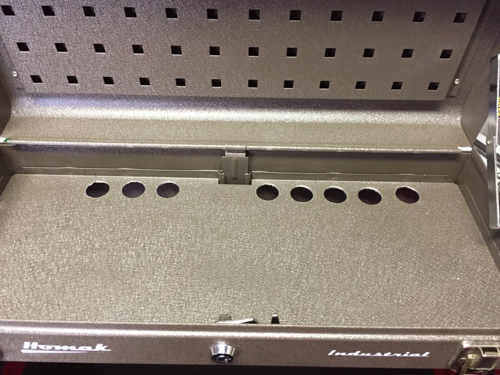
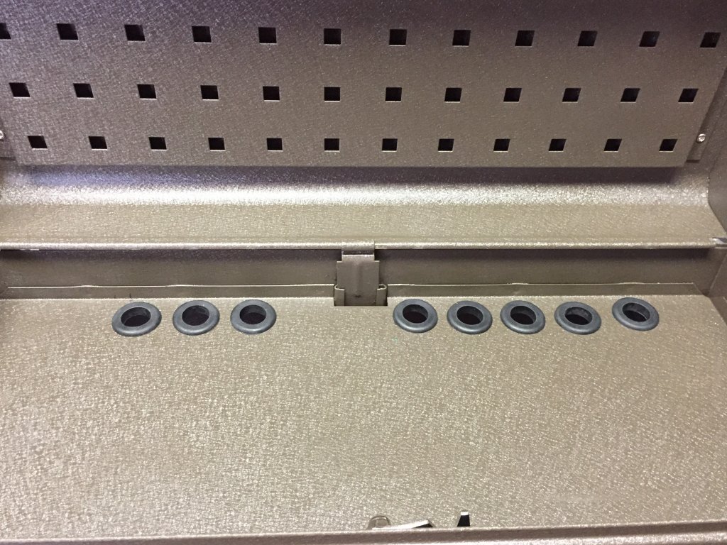
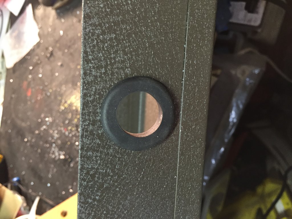
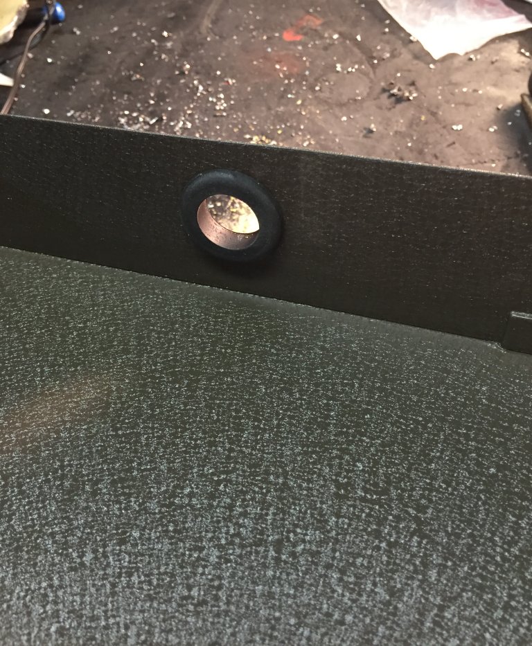
And because these wires will be carrying either DC current or an AC audio signal, and neither of them would benefit from a short-circuit, I need to put grommets in the holes. The biggest grommets I could find at Home Depot were 3/4”, which should work OK, and I thought my 7/8” step drill bit would be fine for that. Then I read the packaging on the grommets and learned that in order to make a 3/4” grommeted hole, the hole in the toolbox was going to need to be 1” in diameter. OK, any excuse to buy new tools. I now have 3 step drill bits, the largest of which goes up to 1-3/8” in diameter. Woo-hoo!
As I think I said (at least once), proof of concept on this project is running about 3 days ahead of execution, so there’s some things I think will work that I haven’t tried yet, and haven’t been in a position to try until a preceding step was validated. So the next hurdle is cable management. For each pedal, a pair of ¼” audio cables will run between the control box in the top tray and the pedal (if I’d been thinking, I could have used insert cables and not needed so many jacks, or cable, but I digress), along with a 9V power cable from the Mondo, which I’m tentatively planning to put in the middle drawer. The trick is, I need to make the cable long enough so the drawer can open and close easily, and the spare cable length needs to reliably either retract or at least store itself in the toolbox where it won’t come disconnected, short out, or block the drawers from opening and closing freely. Which begs the question: “How is that going to work?” And so far, my answer is: “I don’t know.”
There are a variety of approaches I could use. The most common and most popular cables to use for pedalboards is George L’s, and at first it looks very attractive because it’s relatively narrow in diameter and easy to create cables with. But it’s also very stiff and doesn’t necessarily go where you want it to when you push it (or push in the drawers in this case). And it’s also relatively expensive. I could use the skinny generic cable I used inside the control box, but I didn’t feel good about using cheap cable in an application that would have to move around a lot.
So while that was in the ponderment stage, I started measuring how long each patch cable would need to be, and almost all of them came up at or about 2 feet. So I thought “Why not buy some pre-made right-angle, 2-foot patch cables? eBay must have those!” And indeed they do. Even color-coded ones. And they don’t cost much. So I bought 2 bags of 6, each a different color so I’d have color-coded pairs. Or so I thought. As it turned out, a couple weren’t quite long enough, so I had to make a few custom ones with some Mogami cable and Switchcraft 226 plugs I had lying around.
Finally got that done and plugged it in. No smoke, that’s good. All the loops work, let’s go for the gold and actually plug a guitar and an amp into it! Guitar signal in, guitar signal out! Start switching the loops in and out, yup, I can hear that the compressor is doing what it’s supposed to, so’s the boost, the overdrive, the delay, and the EQ. Cool! Tremolo…hmm. Switching it in and out doesn’t seem to make any difference. That’s odd. Listening closely, I can hear the relay pull in and out when I hit the switch. Must be a short inside the box. I had visions of trying to re-solder the little wires I’d used on the perf board, or searching for an errant blob of solder somewhere, it wasn’t going to be fun. So in an effort to avoid that, I looked at other stuff first. When I started running out of space for jacks on the sides of the box, I put a couple on top for loop 6, which was the tremolo loop. I’d had to move one of the power jacks from its original location between the In and Out jacks on the end side, so I use the hole it used to reside in for the loop 6 send (or was it receive?), and a hole on top for the other jack for that loop, leaving one empty hole on top for, er, ventilation, yeah, that’s it.
So I pulled the control box up off its Dual Lock and pulled the cover off. Now I’d only looked at it this way before with nothing plugged into it. This time, though, I had all the plugs in it, and in this situation, I noticed that the contacts for tips of the plugs in loop 6’s send and receive jacks…were touching. So the relay worked, but its effect was negated by the short. All I had to do was rotate one of the jacks a little and that problem was solved. But now instead of no tremolo, I got a big nasty hum whenever I invoked the loop 6. Cable? Yup. One of my bargain 2-footers went bad. Luckily I had a spare, but so much for color coordination. With an 8.3% failure rate on installation, I suspect there will be more Mogami and less color here as time goes on.
Another accomplishment, another challenge. Finally got all the audio cables made and installed. Got all the power cables installed and labeled. Got the IEC inlet installed. Plugged in the power and everything lights up. Tried to close the drawers and the middle one won't go all the way in. Sigh. Lots of cables back there, so they'll need a bit of rearrangement. I pushed the cables into the most out-of-the-way positions I could and discovered that opening and closing the drawers a few times caused most of the cables to follow the path of least resistance and gradually settle out of the way. The middle drawer still puts up a little struggle, so I think I’m going to have to pull it out and cut a bigger accommodation for the IEC inlet. Don’t want the repeated openings and closings of that drawer to eventually wear the insulation off the inlet’s lugs. That would make things a little smoky, then non-functional.
But for now, it works! Going to be a little while before I brave a gig, or even a rehearsal with it, though. I still need to armor the CAT6 and volume pedal cables for stage durability, I just ordered a PedalPython kit to aggregate them into one black snake that will stand up to the abuse it’s likely to receive. Oh, and I haven’t glued the little rubber corners that came with the toolbox on the bottom to keep it from unduly scratching things up or getting scratched. And I’m researching the feasibility of converting it to wireless switching. Gonna be a while on that one.
Here are some other pictures from the project that I either forgot to write about or didn't add much value to the narrative:
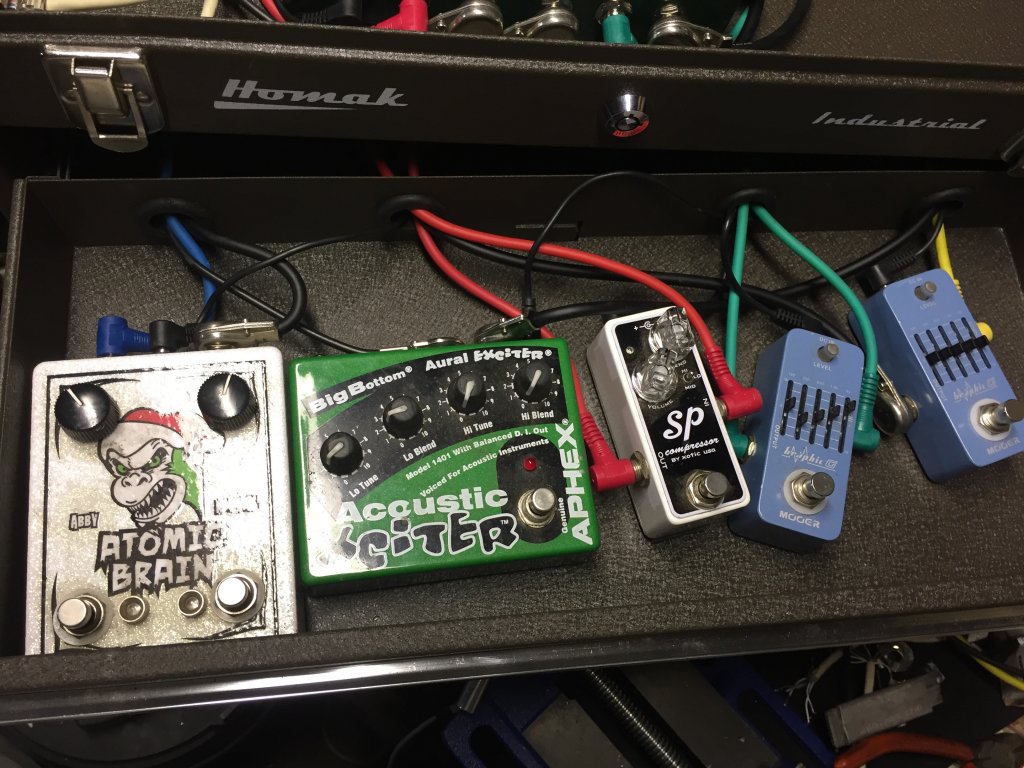
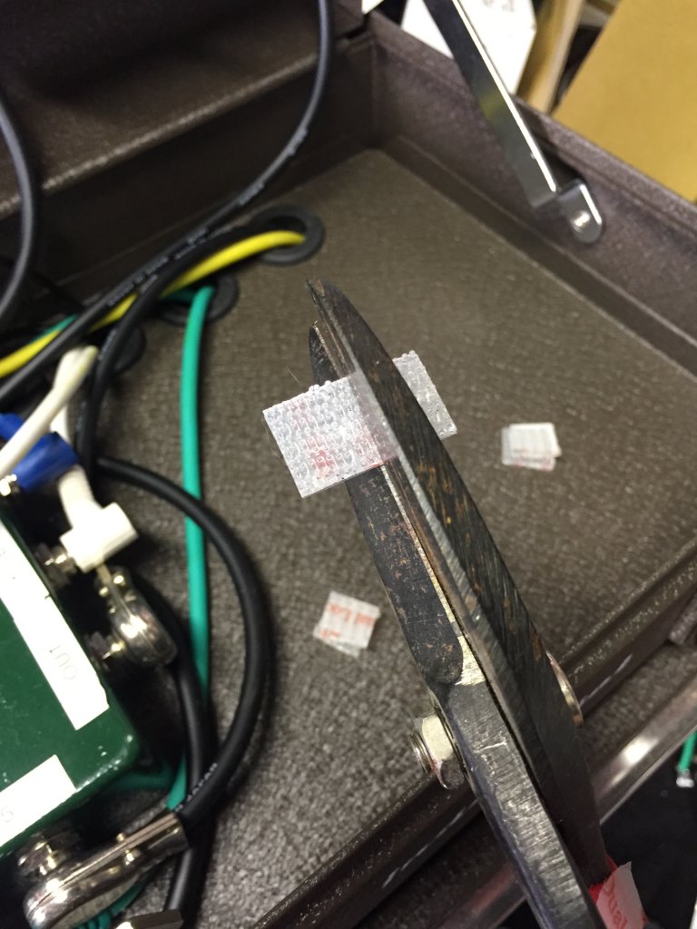

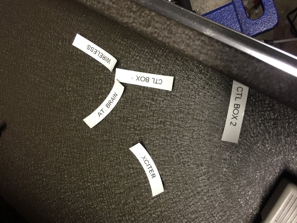
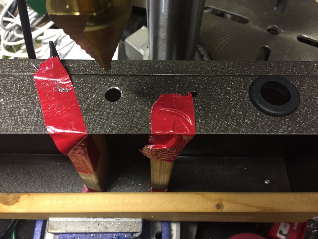

From Last Year:
Hi, folks, and welome to my first blog post. I'll be posting music-related (and other) commentary and the occasional pontification. I'm looking forward to it, hope you are, too.
I'm using GoDaddy's web site designer to facilitate building this site. As part of the design process, they provide templates and themes to get you going. The one I chose is called "Stout." I can't help but wonder if Jonathan had anything to do with it.
While you're here, let me ask for your help on a project: What would you like to see in the way of video demos? Product demos? Techniques? How to play particular songs? Let me know and it will guide my choices for what videos I create. Thanks!
FG
September 21, 2016 (Wednesday)
OK, it's time for me to be a tease. A couple weekends ago I was at the Northern California Gretsch Roundup with a bunch of my fellow Gretsch-o-philes and one of them approached me with the notion of trying out a new product he was making, and blathering about it if I liked it (or didn't). Now if you know me, you know I'd jump at the chance to do something like that, and, not surprisingly, I did. But he hasn't given me formal approval for disclosing what we're up to, so I'm just going to have to post a picture he sent me today of the first component:
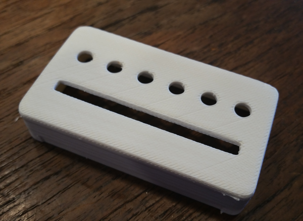
So far, I think we're off to a great start.
FG
November 5, 2016
I tend to go through cycles, wherein I'll use one pedalboard for most everything for a long time, and then I'll think about my other boards and decide to bring one out and try it for my current needs. Recently, my old country band re-formed, and I thought I'd try my Roland VG-99 guitar uber-processor and augmented FC-300 foot controller and see if I could make patches for every different song I'd need different patches for. With this band, that's kind of a tall order, because we've got clean electric in standard tuning, clean and dirty electric in Drop-D, real dirty electric in C#, a song that switches back and forth between standard tuning (down 1/2 step) and Open-Eb, Acoustic, Acoustic tuned down a whole step, B-Bender, 12-string acoustic, Drop-D acoustic, even a virtual capo. Oh yeah, and bagpips for the intro to "Copperhead Road." And I'd rather not bring that many guitars. The VG-99 can handle it, so I spent a couple days programming it, which is kind of fun once you get started, because you can tweak the living daylights out of it.
And off to rehearsal I went. Not sure what went wrong, but an awful lot of the pedals I'd programmed didn't work, the levels were all goofy, I hung my head in shame and started to think analog pedals aren't all that much fuss. I had been contemplating using the VG at an upcoming gig but after that rehearsal, I scrapped those plans. Then the weekend came along and I thought about my other pedalboard with the Boss GP-10 guitar processor and some fundamental boutique pedals on it. The Boss is a newer unit, and the guitar and effect models are more sophisticated, even though the feature set is more limited. But I got all the patches I need set up, even a set I can use with the Lizards, and found a problem pedal (my former secret weapon, the Aphex Acoustic Xciter; it always makes my all-analog board sound better, but it was blowing up the acoustic patches on this one) so I yanked it.
With all this newfound real estate, I pondered what I could put on the board in its place. I decided my Diamond compressor, one of the best pedals I've ever used, was the likely candidate, and I thought a buffer might be a good thing to have at the end of the pedal signal chain, so I pulled the TU-3 tuner (now I have 3 of those I'm not using) and put an LS-2 at the end. Pedalboard perfection:
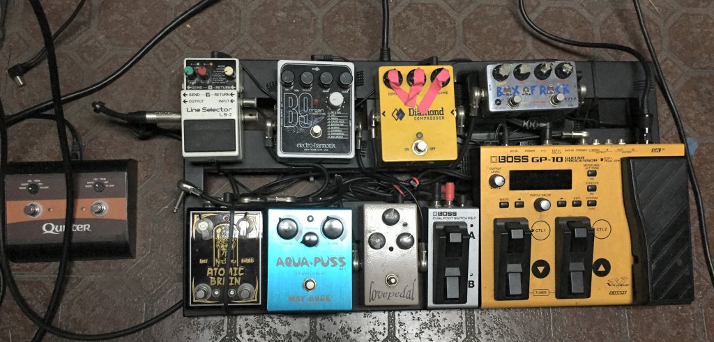
This was an afternoon well spent. Can't wait for the next rehearsal. I'm even thinking of taking it to the gig on Tuesday.
December 11, 2016
A couple of things happening. After talking with Mel about those pickups he's building for me, we've changed the pickup covers a little. Now instead of being all white, they're chrome-edged with white bobbins. Open coil, sorta, but better looking than the usual open-coil humbuckers.

But wait, there's more! I got a new amp!

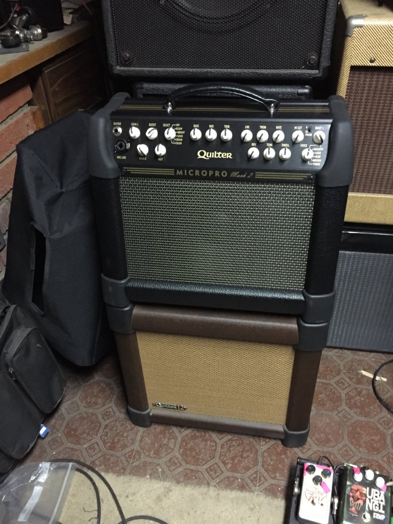
I've been telling myself that the newer Quilter, the MicroPro Mach II, was great and all, but my original MicroPro was great enough for me. And it is. But over Thanksgiving, deals were available, and I succumbed. So now I've got it. And yeah, it's not a lot different, but it sure sounds good. Hate to let go of my original MP, we've been through a lot together, but I have to pay for the new one somehow.